Section 2
Installation
20412922
8-2012/Rev 10
2-8
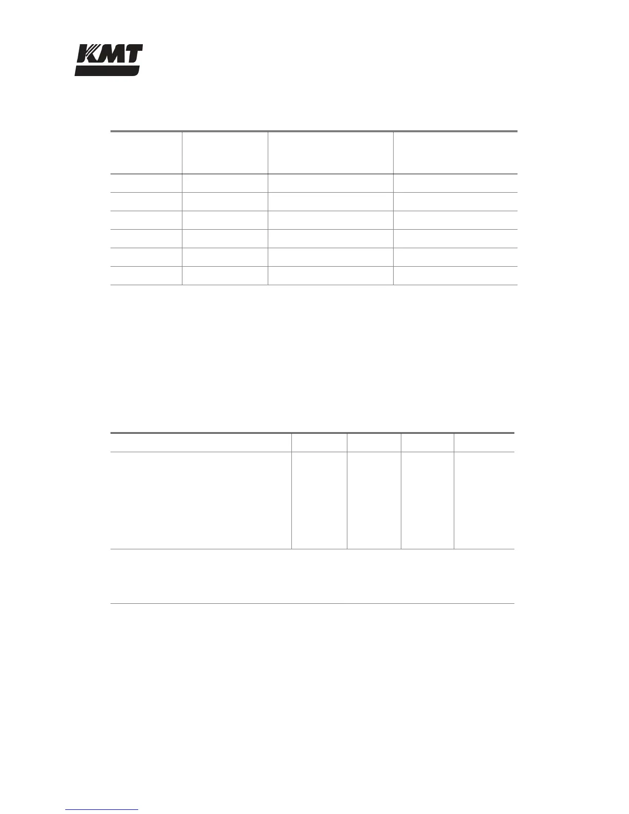
Table 2-6
ISO Air Quality Classifications
ISO Quality
Class
Maximum
Particle Size
(microns)
Maximum Pressure
Dew Point
(water @ 100 psi)
Maximum Oil Content
(Mg/m
3
)
1 0.1 -94° F (-60° C) 0.01
2 1 -40° F (-40° C) 0.1
3 5 -4° F (-20° C) 1
4 15 +38° F (+3° C) 5
5 40 +45° F (+7° C) 25
6 -- +50° F (+10° C) --
Contaminated Waste Drain
Oil and water that can accumulate on the top pan is disposed of through the contaminated waste
drain. This oil and water mixture is considered contaminated and disposal must comply with
local, regional and national codes. The volume of waste will be minimal and can be collected in a
container of some appropriate type.
Table 2-7
Service Connection Specifications
30 HP 50 HP 60 HP 100 HP
Cooling Water (oil-to-water models)
Maximum consumption at 75 F (24 C)
[gpm (L/min)]
2.5 (9.5) 3.0 (11.4) 3.5 (13.2) 4.5 (17.0)
Cutting Water
Maximum consumption
[gpm (L/min)]
2.5 (9.5) 4.0 (15.1) 4.5 (17.0) 8.0 (30.0)
Minimum inlet cooling water pressure 35 psi (2.4 bar)
Minimum inlet cutting water pressure 35 psi (2.4 bar) flowing
Minimum compressed air pressure 85 psi (5.9 bar)
2.6 Flow Requirements
Figure 2-4, Pressure Drop Values, illustrates the pressure drop for four different pipe sizes. The
graph can be used to calculate the minimum source water pressure.
1. Enter the graph at the required GPM and note the pressure drop figures for the different
pipe sizes.
2. Multiply the pressure drop (PSI/FT) by the length in feet of each pipe size used from the
water source to the intensifier. Add the values together for a total pressure drop value.

 Loading...