Section 8
Electrical System
20412989
1-2012/Rev 08
8-10
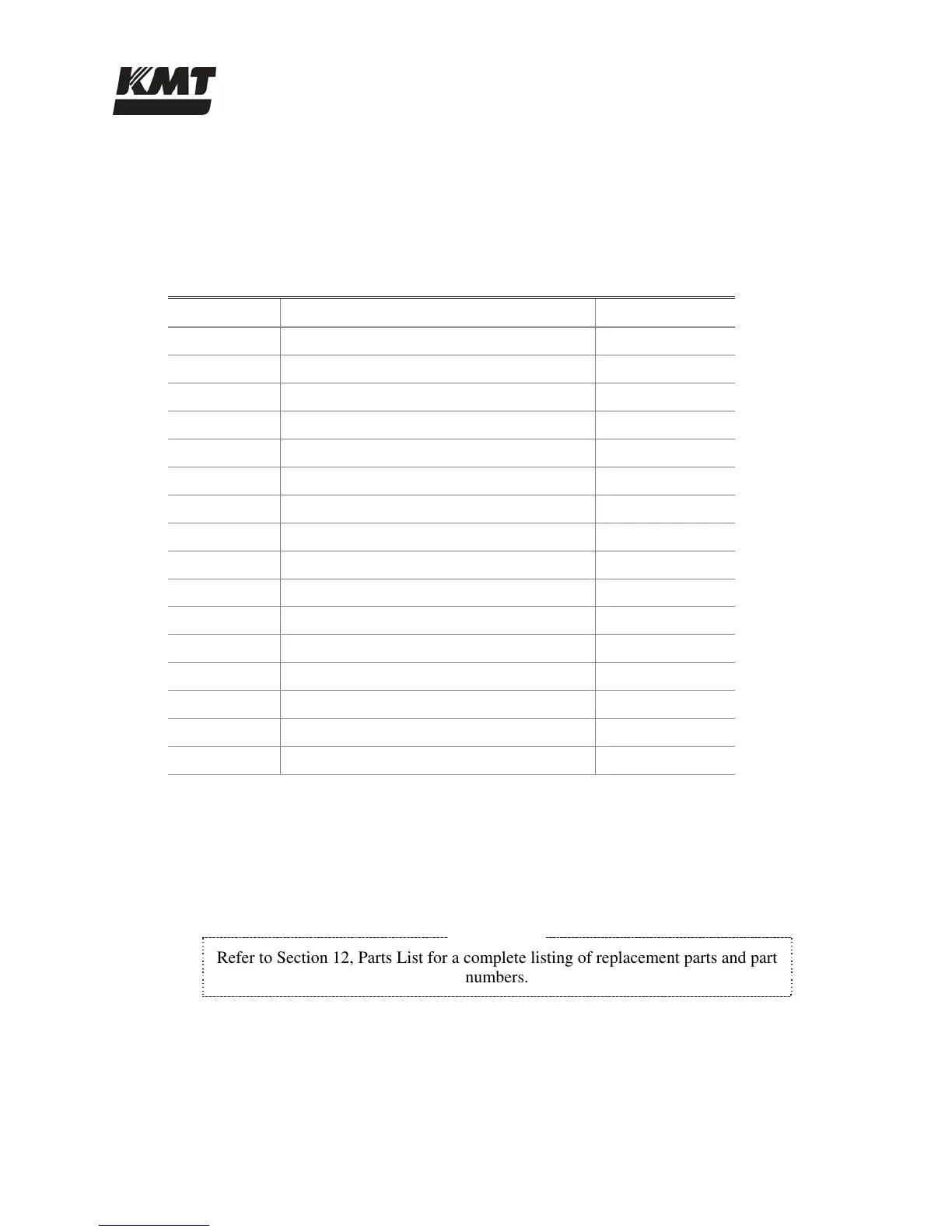
DIP Switch Settings
DIP switches are used to set the start/stop profile, overload trip class and auxiliary contact
characteristics. Open the tab on the top, right of the softstarter to access the eight DIP switches.
Table 8-2 illustrates the switch settings, starting from the left.
Table 8-2
DIP Switch Settings
Number Setting Position
1 Start time (2 seconds) Down
2 Start time (2 seconds) Down
3 Soft Start Up
4 Current limit above Full Load Amps (250%) Down
5 Current limit above Full Load Amps (250%) Up
6 Soft Stop Down
7 Soft Stop Down
8 Start Time Down
9 Kick Start (450%) Down
10 Kick Start (450%) Down
11 Trip Class Up
12 Trip Class Down
13 Overload Reset (Auto) Up
14 Aux (Normal) Down
15 Lone or Delta (Delta) Down
16 Phase Rotation (Disabled) Up
8.4 Service and Maintenance Procedures
Electrical components require minimal service. The proximity switches on the hydraulic cylinder
and the optical relay switches in the controls subassembly may require replacement.
NOTE
Refer to Section 12, Parts List for a complete listing of replacement parts and part
numbers.

 Loading...