Section 5
Low Pressure Water System
20412955
8-2012/Rev 08
5-5
4. Install the new element over the rod in the center of the housing.
5. Apply FML-2 grease to the gasket in the filter head and to the gasket on the cap nut.
6. Position the housing in the filter head and install the cap nut.
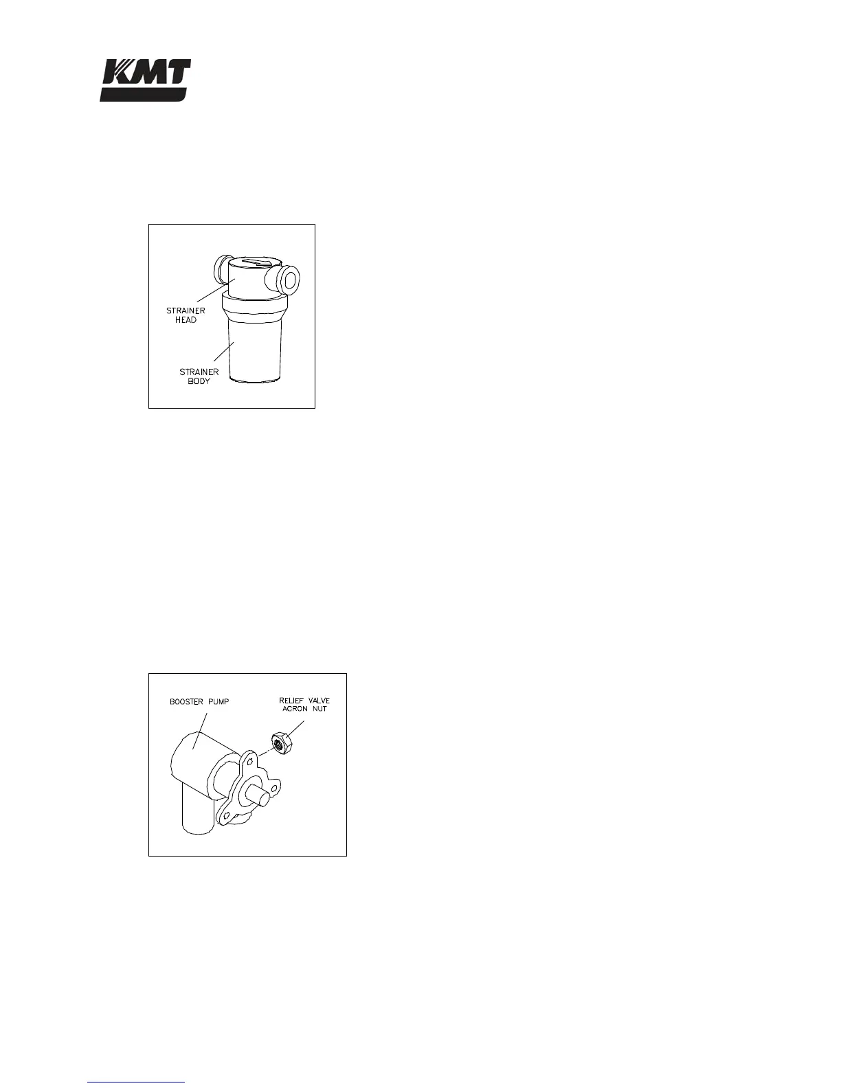
Figure 5-4: Strainer
7. Unscrew and remove the strainer body. Remove and clean the mesh liner.
8. Ensure the gasket is properly positioned in the body, install the liner and screw the strainer
body into the strainer head, hand tighten.
9. Turn the cutting water supply on.
10. Press the red bleed valve to remove any air inside the housing.
11. Start the machine and verify satisfactory pressure readings.
Booster Pump Adjustment
If the discharge pressure from the booster pump stays below 90 psi (6 bar) while the intensifier is
shifting, the relief valve on the booster pump should be adjusted.
Figure 5-5: Booster Pump
1. Turn the cutting water supply on.
2. Start the machine and initiate normal, shifting operation.
3. Observe the discharge pressure from the booster pump. If the pressure stays below 90 psi
(6 bar), continue with Step 4.

 Loading...