Section 9
High Pressure Water System
20412997
8-2012/Rev 12
9-28
7. Remove the hydraulic cylinder head with the o-ring and backup ring. The mounting flat
for the proximity switch provides a small lip for loosening the cylinder head.
8. Grasp the plunger firmly and pull the piston out of the hydraulic cylinder.
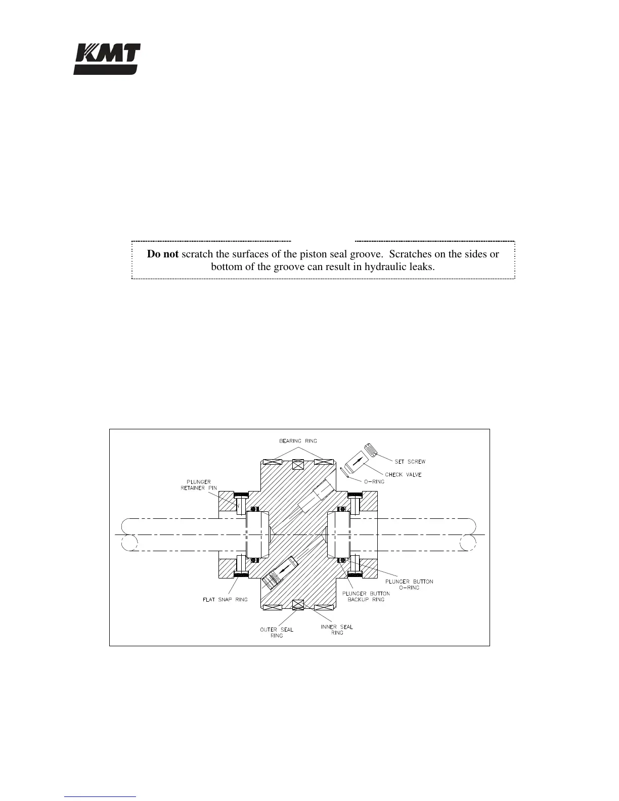
Bearing Rings and Seal Assembly
1. Remove the plungers.
2. Use a smooth, dull-edged blade made from brass or similar soft metal material to remove
the two bearing rings and the seal assembly.
NOTE
Do not scratch the surfaces of the piston seal groove. Scratches on the sides or
bottom of the groove can result in hydraulic leaks.
3. Inspect the bottom of the seal grooves for marks, scratches and residue buildup. Clean
and/or repair the groove surfaces as required.
4. Apply FML-2 grease to the new bearing rings and install the rings.
5. The piston seal assembly consists of an inner and an outer seal ring. Apply FML-2 grease
to both rings. Use the smooth, dull-edged blade to install the inner ring, ensuring the ring
is not twisted after installation. Slide the outer seal ring over the metal edges and ease it
into position over the inner ring.
Figure 9-21: Hydraulic Piston
Plunger Button Sockets, Seals and Retainer Pins
1. Remove the flat snap rings and plunger retainer pins on both ends of the piston.
2. Inspect the snap rings and the pins for unusual wear or deformation. Clean and inspect the
pin holes for unusual wear, deformation or hole enlargement.

 Loading...