FIXING UNIT
2-O-4
2 UNIT EXPLANATION
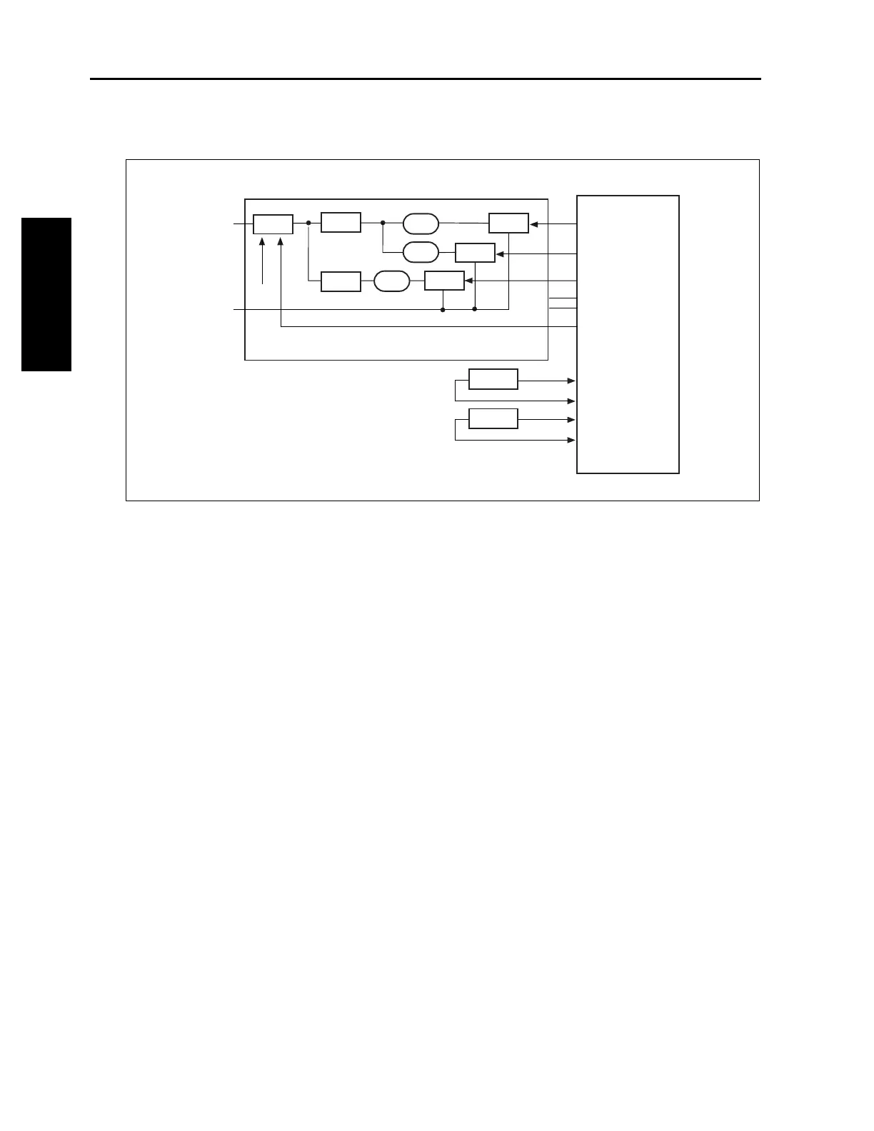
[4] Fixing Temperature Control
The fixing roller (upper) is heated by L2 (fixing
heater lamp 1) and L3 (fixing heater lamp 2) and
the fixing roller (lower) is heated by L4 (fixing
heater lamp 3). The PRCB (printer control board)
detects the temperature of the fixing roller
(upper) using TH1 (fixing temperature sensor/1)
TH2 (fixing temperature sensor/2) and controls
L2 and L3 via DCPS (DC power supply unit).
1. Operation
a. Temperature control
The PRCB (printer control board) turns ON the
fixing heater lamp circuit in DCPS as soon as the
SW2 (sub power) is turned ON, holding L2 (fixing
heater lamp/1), L3 (fixing heater lamp/2), and L4
(fixing heater lamp/3) lit until the fixing roller
(upper) reaches the specified temperature. L2,
L3 and L4 are turned ON/OFF under the control
of the TRC1 (triac/1 ), TRC2 (triac/2) and TRC3
(triac/3).
b. Protection against abnormal temperature
rise
Thermostats are used to prevent the tempera-
ture of the fixing rollers from rising abnormally.
TS1 (thermostat/U) and TS2 (thermostat/L) are
used for the fixing roller (upper/lower). As these
thermostat are of the noncontact type, those do
not touch the fixing roller (upper/lower).
The operating temperature of the thermostats
are as follows:
TS1: Opens at 356°F
TS2: Opens at 230°F
2. Signals
a. PRCB input signals
(1) TH1+,- (TH1 to PRCB)
Fixing roller (upper) temperature detection sig-
nal
This signal is used to control the temperature of
the fixing roller (upper) and to detect abnormal
temperature rise.
(2) TH2+,- (TH2 to PRCB)
Fixing roller (upper) temperature detection sig-
nal
This signal is used to detect the fixing roller
(upper) abnormal temperature rise.
DCPS
PRCB
FIXHT1_CONT
FIXHT2_CONT
FIXHT3_CONT
MAINRL_CONT
AC(H)
AC(C)
TH1+
TH1-
TH2+
TH2-
5V2
S.GND
TH2
TH1
TRC1
RL1
L3
L4
L2
TS1
TRC2
TRC3
24VDC
TS2