OTHER ADJUSTMENT
1 ADJUSTMENT
MODEL MANUAL REVISED EDITION DATE PAGE METHOD
SERVICE HANDBOOK May 20027155/7165
[26] PK Adjusting the punch hole vertical
position (PK-110)
Caution1: Perform this adjustment after finish-
ing the adjustment for the tilt of the
punch hole position.
Caution2: Complete the PK adjusting the
punch hole vertical position feeding
the paper from the by-pass tray first.
Then, perform this adjustment feed-
ing paper from the tray that is most
frequently used.
Caution3: If there is a difference in the punch
hole vertical position, perform the
centering adjustment for the trays of
main body or PI.
1. Tool
• Screwdriver (Phillips)
•Scale
2. Adjustment method
a. Preparation
b. Adjustment
Step Operation
1
Check the following items:
• The finisher is connected to the main
body.
• The main body is loaded with the
paper based on the punch specifica-
tions.
2
Check the skew of output paper in
advance.
Slide the side guide plate and the rear
guide plate for the main body's feed tray,
and align the paper loaded on the main
body's tray.
3
Make three copies each in single side
copy mode and double side copy mode
with the punch mode to check the posi-
tion of the holes.
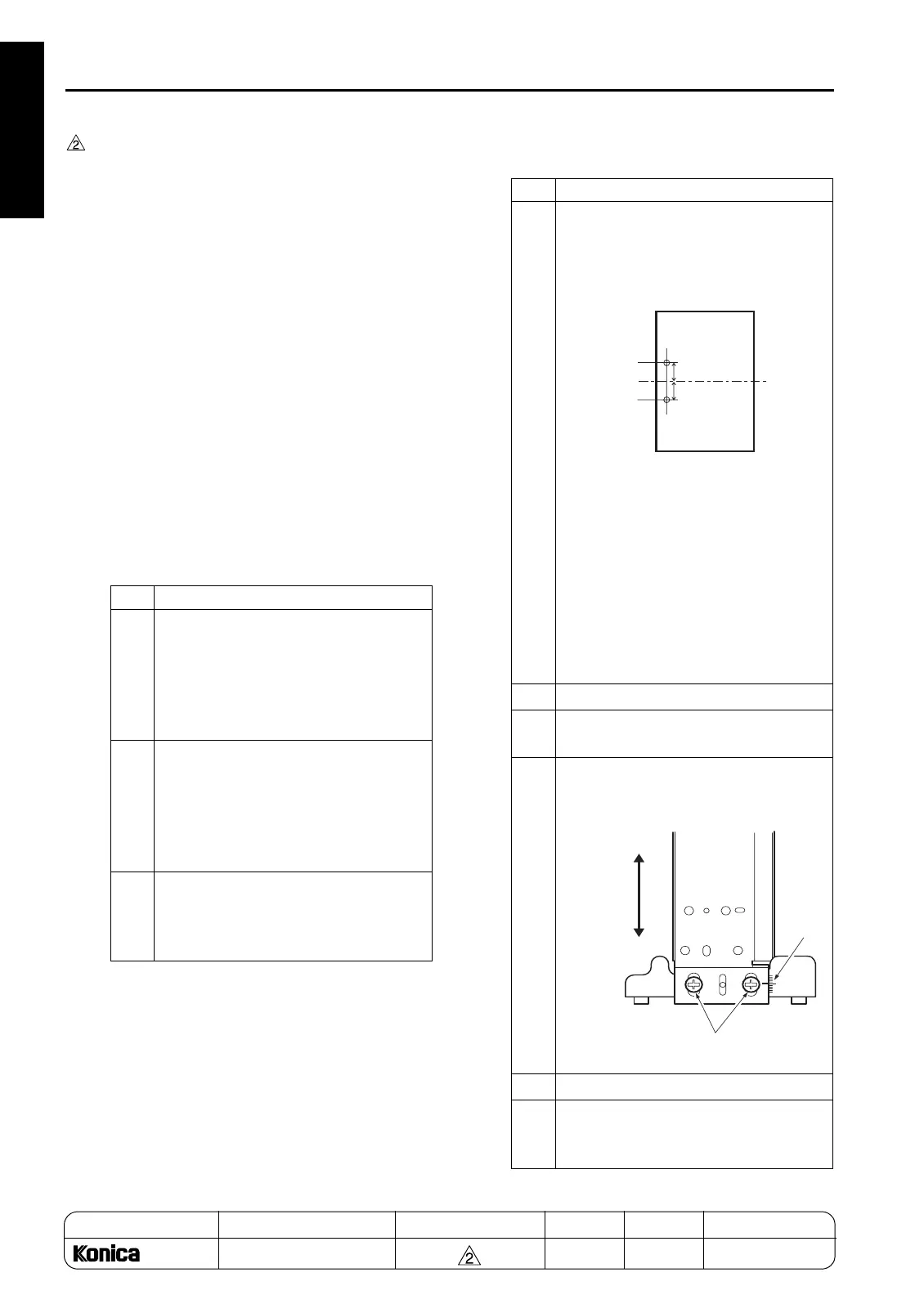
Step Operation
1
Fold the sample at the middle of the
paper, check the position of each punch
hole, and calculate the dimension to be
adjusted.
Specified limit: (A-B) Error of position of
the two punch holes))/2
Reference: For adjustment of the
punch hole vertical posi-
tion, the dimension of the
punch hole vertical position
can be adjusted by
±
5mm.
Adjusting the hole pitch is
not allowed.
2
Open the front cover.
3
Loosen the two adjustment screws for
PK.
4
Using the mark scale as a guide, move
the punch unit vertically to 1/2 the dis-
tance of the above dimension.
5
Retighten the screws.
6
Make a sample copy of punch mode and
recheck the discrepancy of the punch
hole vertical position.
A
B
Adjustment screws
Mark
Adjust
horizontally
1-130
REPLACEMENT