OTHER ADJUSTMENT
1 ADJUSTMENT
MODEL MANUAL REVISED EDITION DATE PAGE METHOD
SERVICE HANDBOOK May 20027155/7165
b. Adjustment
Step Operation
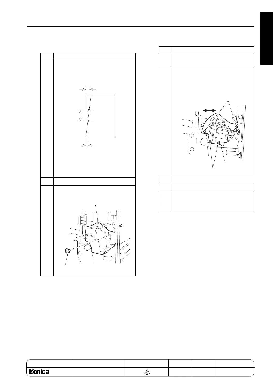
1
Measure the position of the sampled
punch holes to check the tilt of the posi-
tion.
Tilt of the punch hole position:
A-B (Difference in position of the two
punch holes)/C (Distance of hole pitch)
2
Open the front cover.
3
Remove the punch unit cover by remov-
ing three screws.
A
B
C
Screw
Punch unit cover
4
Loosen the four adjustment screws of
PK.
5
Using the mark scale as a guide, move
the punch unit horizontally by the
amount of tilt for the punch hole position.
1 scale: 0.5%
6
Retighten the screws.
7
Reinstall the punch unit cover.
8
Make a sample copy of punch mode and
recheck the tilt of the punch hole posi-
tion.
Step Operation
Mark
Adjustment screws
Adjustment screws
Adjust to the left or right
1-129
REPLACEMENT