OTHER ADJUSTMENT
1 ADJUSTMENT
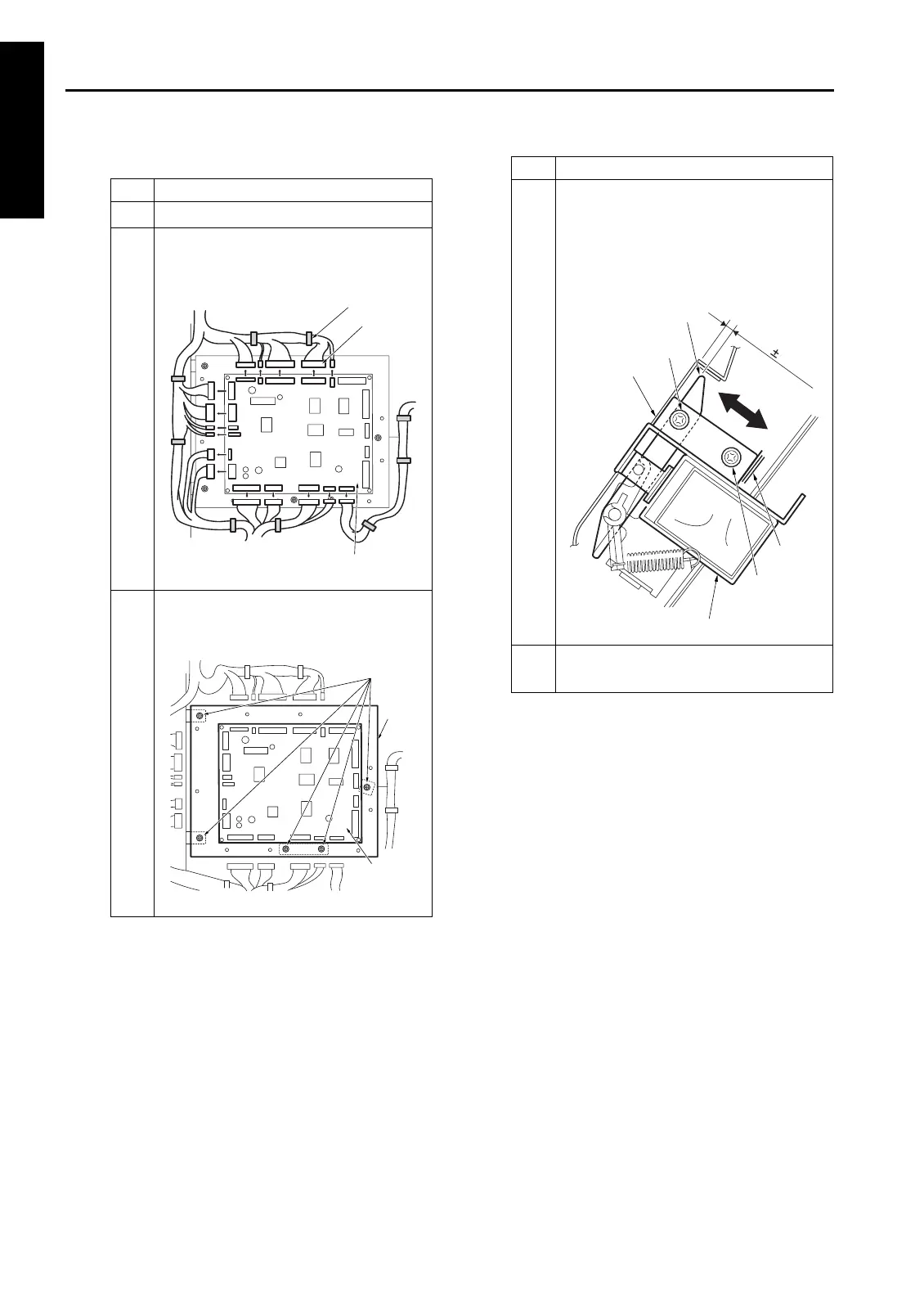
b. Adjustment
Step Operation
1
Take off the rear cover.
2
Remove all cable assembly from the
connectors and clamps connecting to
FNS CB (FNS control board).
3
Remove five screws and detach the FNS
control board (FNS CB) together with its
bracket.
Clamp
Connector
FNS control board
(FNS CB)
Screws
Bracket
FNS CB
(FNS control
board)
4
Loosen two screws securing the by-pass
gate SD (SD705) and adjust the position
of SD705 so that the gap between the
by-pass gate and by-pass conveyance
plate becomes within the standard
value.
5
Reinstall the parts in the opposite
sequence to removal.
Step Operation
A=3.2 0.5mm
Screw
Screw
By-pass
conveyance plate
Mark
By-pass gate SD (SD705)
By-pass gate
1-114