J
J
J
N
J
J
H
3
Modification of Installation Guide for DF-730
The supplied parts with the job separator described on
page 1 are modified as shown below:
[Addition]
N Cover AT................................................................... 1
[Change]
H Fixing plate F ............................................................ 1
I Fixing plate R............................................................ 1
J S Tite screw M4 × 10.......................................9(5J9)
DF-730 安装手册的变更
第 1 页的作业分离器附属品变更如下。
[补充]
N 盖板 AT ................................... 1
[变更]
H 固定板 F ................................. 1
I 固定板 R ................................. 1
J 紧固螺丝 M4 × 10S .................. 9(5 → 9)
2006.2
303KN56760
DF-730 設置手順書の変更
1 ページのジョブセパレータ付属品を以下のよ
うに変更します。
[追加]
N カバーAT ................................. 1
[変更]
H 固定板 F ................................. 1
I 固定板 R ................................. 1
J ビス M4 × 10S タイト ............... 9(5 → 9)
3ページ、手順 3、4 を次のように変更します。
3. 固定板 F(H) と固定板 R(I) を左カバー
(3) にビス M4 × 10S タイト (J) 各 2 本
で固定し、カバーAT(N) をビス M4 × 10S
タイト (J)2 本で固定板 F(H) に固定す
る。
4. ラッチ受け板 (B) をビス M4 × 10S タイ
ト (J)2 本で固定板 F(H) と固定板 R(I)
に固定する。
(手順7に進む)
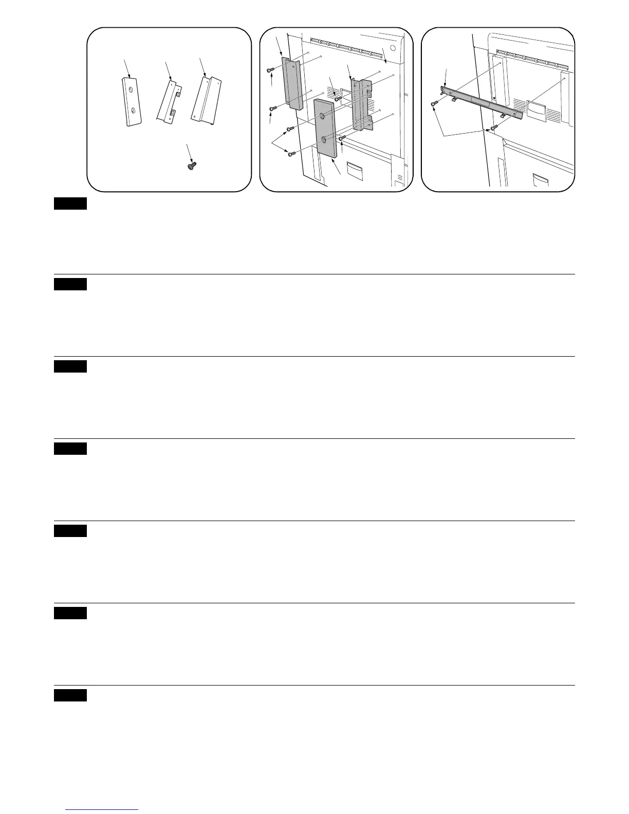
Steps 3 and 4 on page 3 are modified as described below:
3. Fit the fixing plate F (H) and the fixing plate R (I) to
the left cover (3) using two S Tite screws M4 × 10
(J) for each and fit the cover AT (N) to the fixing
plate F (H) using two S Tite screws M4 × 10 (J).
4. Fit the latch catch (B) to the fixing plate F (H) and
the fixing plate R (I) using two S Tite screws M4 ×
10 (J).
(Proceed to step 7.)
Modifications apportées au guide d’installation du DF-730
Les pièces fournies avec le séparateur de travaux
décrit à la page 1 sont modifiées comme montré ci-
dessous:
[Addition]
N Couvercle AT ............................................................ 1
[Changement]
H Plaque de fixation F.................................................. 1
I Plaque de fixation R ................................................. 1
J Vis Tite S M4 × 10 ...........................................9(5J9)
Les étapes 3 et 4 de la page 3 sont modifiées comme décrit ci-dessous:
3. Fixer la plaque de fixation F (H) et la plaque de
fixation R (I) sur le couvercle de gauche (3) à l’aide
de deux vis Tite S M4 × 10 (J) chaque et fixer le
couvercle AT (N) sur la plaque de fixation F (H) à
l’aide de deux vis Tite S M4 × 10 (J).
4. Fixer le cliquet du verrou (B) sur la plaque de
fixation F (H) et sur la plaque de fixation R (I) à
l’aide de deux vis Tite S M4 × 10 (J).
(Passer à l’étape 7.)
Modificación de la Guía de Instalación para DF-730
Las partes provistas con el separador de trabajos
descritas en la página 1 se modifican tal como se
indica abajo:
[Adición]
N Cubierta AT............................................................... 1
[Cambio]
H Placa de fijación F (delantera).................................. 1
I Placa de fijación R (trasera) ..................................... 1
J Tornillo S Tite M4 × 10.....................................9(5J9)
Los pasos 3 y 4 en la página 3 se modifican tal como se describen abajo:
3. Encaje la placa de fijación F (H) y la placa de
fijación R (I) en la cubierta izquierda (3) utilizando
dos tornillos S Tite M4 × 10 (J) para cada una y
encaje la cubierta AT (N) en la placa de fijación F
(H) utilizando dos tornillos S Tite M4 × 10 (J).
4. Encaje el pestillo (B) en la placa de fijación F (H) y
la placa de fijación R (I) utilizando los dos tornillos
S Tite M4 × 10 (J).
(Vaya al paso 7.)
Änderung der Installationsanleitung für DF-730
Die Teile, die im Lieferumfang des auf Seite 1
beschriebenen Jobtrenners enthalten sind, wurden wie
folgt geändert.
[Ergänzung]
N Abdeckung AT .......................................................... 1
[Änderung]
H Fixierplatte F............................................................. 1
I Fixierplatte R ............................................................ 1
J S-Tite-Schraube M4 × 10 ................................9(5J9)
Die Schritte 3 und 4 auf Seite 3 wurden wie folgt geändert:
3. Die Fixierplatte F (H) und die Fixierplatte R (I) mit je
zwei S-Tite-Schrauben M4 × 10 (J) an der linken
Abdeckung (3) anbringen, und die Abdeckung AT
(N) mit zwei S-Tite-Schrauben M4 × 10 (J) an der
Fixierplatte F (H) anbringen.
4. Die Verriegelungsklaue (B) mit zwei S-Tite-
Schrauben M4 × 10 (J) an der Fixierplatte F (H)
und die Fixierplatte R (I) anbringen.
(Zu Schritt 7 übergehen.)
Modifica della guida all’installazione di DF-730
Le parti fornite con il separatore descritte a pagina 1
sono cambiate come si vede qui in basso:
[Aggiunta]
N Coperchio AT............................................................ 1
[Modifica]
H Piastra di fissaggio F ................................................ 1
I Piastra di fissaggio R................................................ 1
J Vite S Tite M4 × 10 ..........................................9(5J9)
I passi 3 e 4 a pagina 3 sono stati modificati nel modo indicato qui in basso:
3. Montare la piastra di fissaggio F (H) e la piastra di
fissaggio R (I) sul coperchio sinistro (3) usando due
viti S Tite M4 × 10 (J) per ciascuna di esse e
montare il coperchio AT (N) sulla piastra di
fissaggio F (H) usando due viti S Tite M4 × 10 (J).
4. Montare il dispositivo di arresto (B) sulla piastra di
fissaggio F (H) e sulla piastra di fissaggio R (I)
usando due viti S Tite M4 × 10 (J).
(Procedere con il passo 7.)
第3页的步骤3、4变更如下。
3. 将固定板 F(H) 和固定板 R(I) 分别用 2 个
紧固螺丝 M4 × 10S(J) 固定在左盖板 (3)
上,将盖板AT(N)用2个紧固螺丝M4×
10S(J) 固定在固定板 F(H) 上。
4. 将止动托板 (B) 用 2 个紧固螺丝 M4 ×
10S(J) 固定在固定板 F(H) 和固定板 R(I)
上。
( 接着操作步骤 7)
 Loading...