2DF
1-3-38
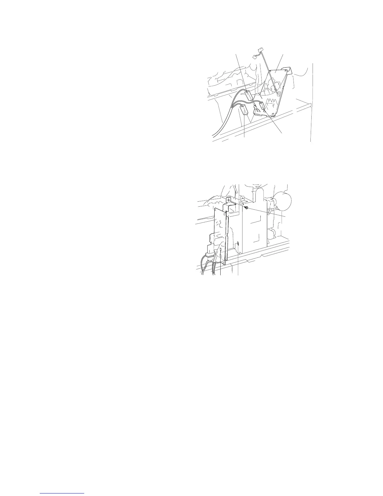
Figure 1-3-72
Catch
M3 × 06 chrome
binding screw
Mount hole
16. Fit the catch on the auxiliary power unit into
the mount hole in the copier, and fasten the
auxiliary power unit into place with one M3 ×
06 chrome binding screw.
15. Connect the three positive connectors on the
power board to the corresponding connectors
on the auxiliary power source PCB, as
follows.
• White positive connector → TB1 (white)
• Green positive connector → TB2 (green)
• White positive connector → TB3
Figure 1-3-71
TB3
TB1
TB2
Auxiliary power
source PCB
Green positive
connector
White positive
connector
White positive
connector
1-3-37-1

 Loading...


