2DF
1-3-46
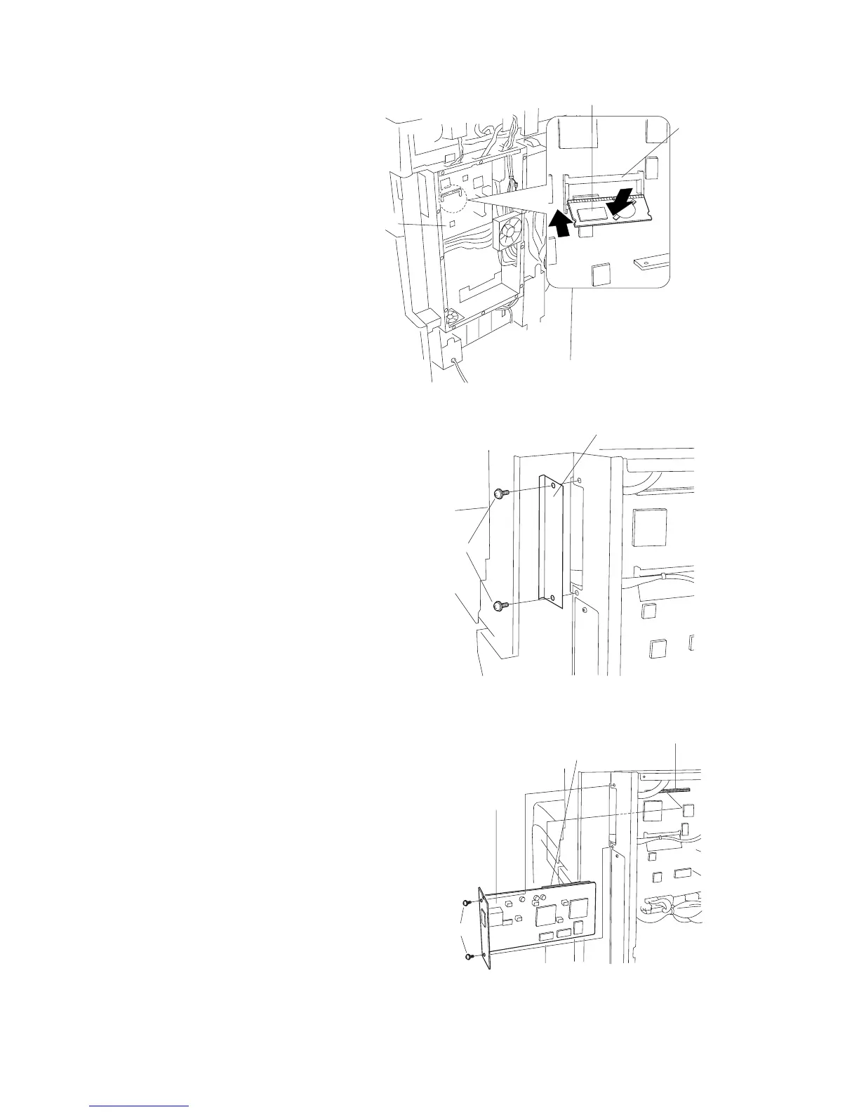
4. Insert the RTC board at an angle into the
RTC board slot on the main PCB.
5. Push the free end of the RTC board down
toward the fax board.
6. Remove 2 screws, and take off the cover.
7. Firmly push connector CN1 on the scanner
board all the way into connector CN50 on the
main PCB.
8. Fasten the scanner board with 2 screws.
Figure 1-3-98
Figure 1-3-96
Figure 1-3-97
RTC board slot
RTC board
Main PCB
Cover
Screws
Connector CN1
Connector CN50
Screws
Scanner board

 Loading...


