2FD/2FF/2FG
1-3-51
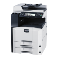
11. Fit the catch on the auxiliary power unit into
the mount hole in the copier, and fasten the
auxiliary power unit into place with one M3 ×
06 chrome binding screw.
Catch
M3 × 06 chrome
binding screw
Mount hole
Figure 1-3-118
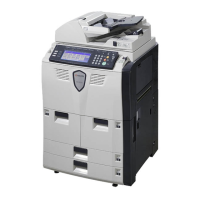
12. Through the opening of controller-box above
the speaker, connect the FAX-PCB-Power
cable on the auxiliary power source PCB
assembly to connector YC8 on the fax board.
13. Connect the 2-pin connector to the 2-pin
connector with green cable.
FAX-PCB-Power
cable
Auxiliary power source
PCB assembly
YC8
Opening
2-pin connector with
green cable
2-pin connector
Fax board
Figure 1-3-119
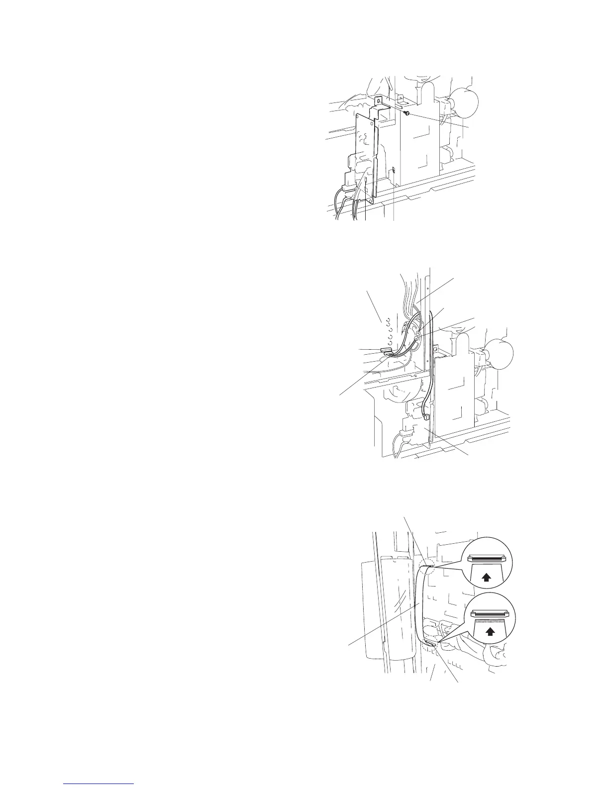
14. Unlock YC1 on the fax board by pulling its
connector housing.
15. Hold the fax cable with its conductive side
facing up, insert it into connector YC1, then
push the housing back in to lock the
connector.
16. Hold the other end of the fax cable with its
conductive side facing down, and connect it
to connector YC44 on the main PCB. (Pull
the YC44 housing out to release the
connector lock, then insert the cable, and
then push the housing back in.)
Important: Be sure to push the fax cable all
the way in, and be sure that the connection is
straight. A poor connection may result in a
variety of problems.
Figure 1-3-120
YC44
YC1
Fax board
Fax cable
YC1
YC44

 Loading...