2FD/2FF/2FG
1-3-50
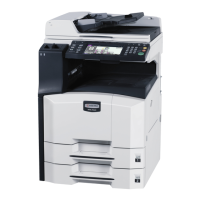
8. Remove the film that fixes the three positive
connectors of the power source PCB from the
optional interface mounting plate.
Important: Dispose of the film that has been
removed.
Film
Optional interface
mounting plate
Figure 1-3-115
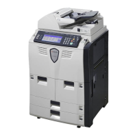
9. Connect the FAX-PCB-Power cable to
connector CN1 on the auxiliary power source
PCB assembly.
CN1
FAX-PCB-Power cable
CN1
Auxiliary power source
PCB assembly
Figure 1-3-116
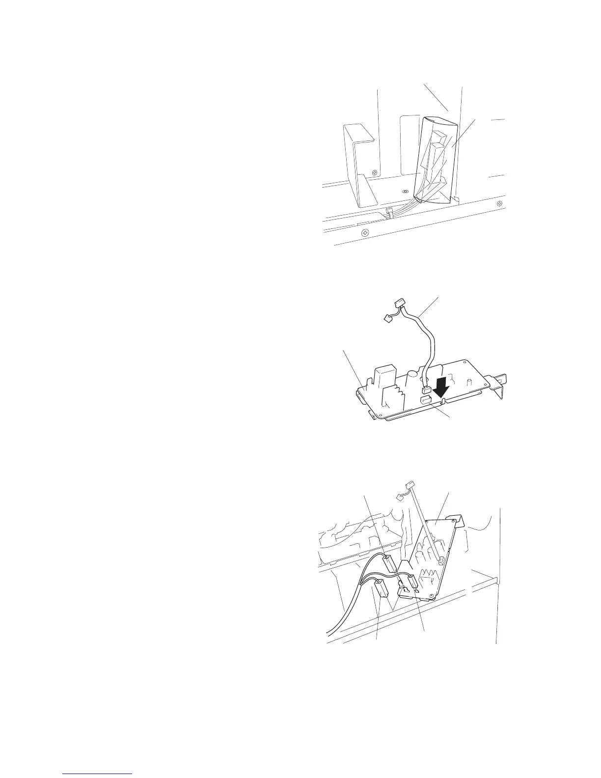
10. Connect the three positive connectors on the
power board to the corresponding connectors
on the auxiliary power source PCB assembly,
as follows.
• White positive connector → TB1 (white)
• Green positive connector → TB2 (green)
• Small white positive connector → TB3
TB3
TB1
TB2
White positive
connector
Auxiliary power source
PCB assembly
Small white positive
connector
Green positive
connector
Figure 1-3-117

 Loading...