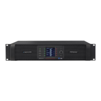
Front Panel Interface
49
PLM Series Operation Manual rev 1.1.9
7.11.2.5 Limiters
MENU > MODULE > LIMITERS
Various parameters of the PLM’s Inter-Sample Voltage Peak Limiter (ISVPL) and the Lake LimiterMax pa-
rameters can be adjusted via this submenu. By default, simultaneous adjustment of most limiter parameters
across all output channels is selected, although channels may be adjusted individually if required. Attack and
Release times must be adjusted individually per channel.
Inter-Sample Voltage Peak Limiter Threshold (ISVPL Threshold)
The ISVPL prevents the voltage of the PLM outputs from exceeding a pre-determined value. The ISVPL
Threshold can be adjusted between 17.8 V to 600 V, which represents the instantaneous peak voltage,
not the RMS value of the output signal. The actual value is displayed in brackets and can be limited by the
maximum voltage a particular PLM Series model can produce.
Inter-Sample Voltage Peak Limiter Prole (ISVPL Prole)
Selecting the ISVPL Prole will optimize the ISVPL limiting for the specic frequency band. ISVPL Prole
permits individual adjustments per channel between two proles; UNIVERSAL and SUB/LF. These two
proles provide differing attack and release times for the ISVPL Limiter and Voltage Clip feedback, with
SUB/LF being more suitable for subwoofers or very low frequency drivers.
The default ISVPL Proles differ depending on the PLM Series model:
▸ PLM 10000Q / 20000Q: UNIVERSAL
▸ PLM 14000: SUB/LF
MaxPeak Level (MaxPeakLvl)
This sets the maximum peak signal level at the Module outputs. It is adjustable from -30 dBu to +30 dBu
in 0.1 dB increments, subject to user-dened level limits. The Group total is displayed (in brackets) for each
channel.
MaxRMS Level (MaxRMSLvl)
This sets the maximum RMS signal level at the Module outputs. It is adjustable from -30 dBu to +30 dBu
in 0.1 dB increments, subject to user-dened level limits. The Group total is displayed (in brackets) for each
channel.

 Loading...