26
Signal Flow and Lake Processing
PLM Series Operation Manual rev 1.1.9
6. Signal Flow and Lake Processing
6.1 Signal Flow
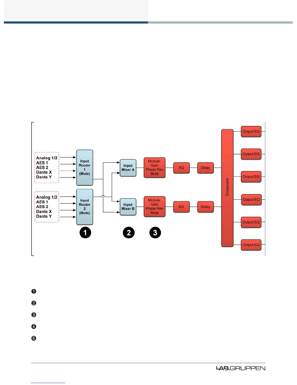
Figure 6-1 and Figure 6-2 depict the audio signal ow inside a PLM. It is worth noting that this sophisticated
device provides seven points in the signal chain where the signal level can be adjusted, muted or discon-
nected.
Important information regarding correct setting of the gain structure can be found in section 10.3.
Figure 6-1: Signal Flow Diagram (PLM Series Part 1)
6.1.1 Level Adjustments & Mute Points
Input Router Stage - Input selection and MUTE
Input Mixer Stage - Router ON/OFF connection to mixer and gain settings
Module Input Stage - Mute and gain settings
Module Output Stage - Mute and gain settings
Output Router Stage - Output ON/OFF routing connections

 Loading...