28
Signal Flow and Lake Processing
PLM Series Operation Manual rev 1.1.9
been rectied or the incorrect setting has been readjusted. Sensing circuits also transmit local output power
stage temperature, processor card temperature, and PSU temperature to the appropriate protection circuits.
Please refer to section 5.3 on page 18 further details.
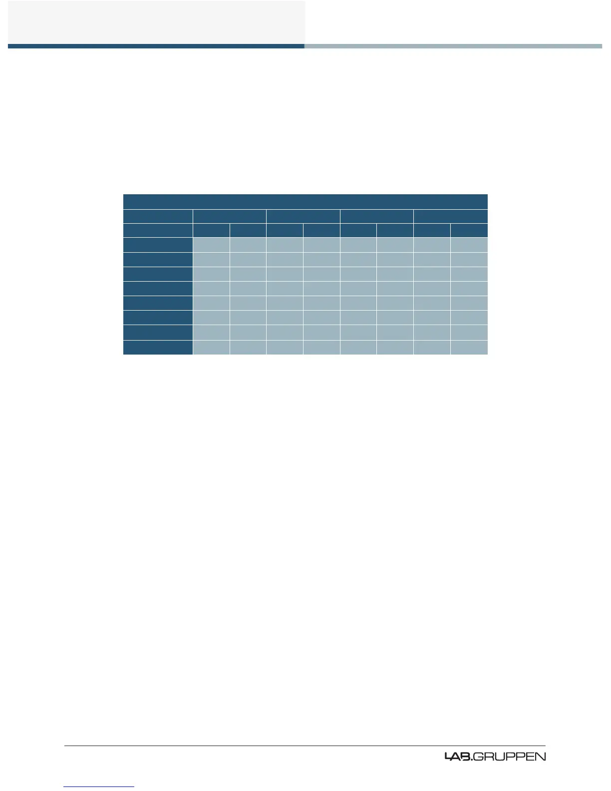
Table 8.1 lists PLM Series analog input sensitivity in dBu and Vrms for various Amp Gain settings and
maximum/minimum ISVPL settings, assuming an analog input headroom of 26 dBu. Please refer to on page
58 for further details.
INPUT SENSITIVITY
ISVPL SETTING 194 V 193 V 153 V 17.8 V
GAIN (dB) dBu Vrms dBu Vrms dBu Vrms dBu Vrms
+44
+1.0 0.87 +0.9 0.86 -1.1 0.68 -19.8 0,08
+41
+4.0 1.22 +3.9 1.22 +1.9 0.96 -16.8 0.11
+38
+7.0 1.73 +6.9 1.72 +4.9 1.36 -13.8 0.16
+35
+10.0 2.44 +9.9 2.43 +7.9 1.92 -10.8 0.22
+32
+13.0 3.45 +12.9 3.43 +10.9 2.71 -7.8 0.32
+29
+16.0 4.87 +15.9 4.84 +13.9 3.84 -4.8 0.45
+26
+19.0 6.88 +18.9 6.84 +16.9 5.42 -1.8 0.63
+22
+23.0 10.90 +22.9 10.84 +20.9 8.59 +2.2 1.00
Table 6-1: Analog Input Sensitivity in dBu and Vrms
6.2 Lake Processing and Control
As outlined in section 2.2.3, this device integrates seamlessly into the Lake Processing environment,
providing all features, functionality and connectivity associated with all Lake Processors. The internal Lake
Processing includes programmable crossovers, EQ, dynamics and other functions, and can be fully con-
trolled via the supplied Lake Controller software. Additionally, many functions can be controlled or accessed
directly via the front panel.
The Lake Controller Operation Manual and Lake Network Conguration Guide are supplied on the accompa-
nying CD ROM and additional documentation is available from the Start Menu after software installation.
6.3 Modules and Frames
6.3.1 Overview
A Frame represents one physical Lake Processor (e.g. a PLM or LM 26). A maximum of two Modules are
contained within each Frame; these are referred to as Module A and Module B. The number of Modules
shown in a given Frame is dependent upon the signal processing conguration of that Frame.
Each Module can be congured as a Classic Crossover (Bessel, Butterworth, Linkwitz-Riley), as a Linear
Phase Crossover, or as multiple full bandwidth Auxiliary Outputs. The default conguration for the PLM is
2 x 2-Auxiliary Output Modules, providing a total of four module outputs.

 Loading...