Signal Flow and Lake Processing
27
PLM Series Operation Manual rev 1.1.9
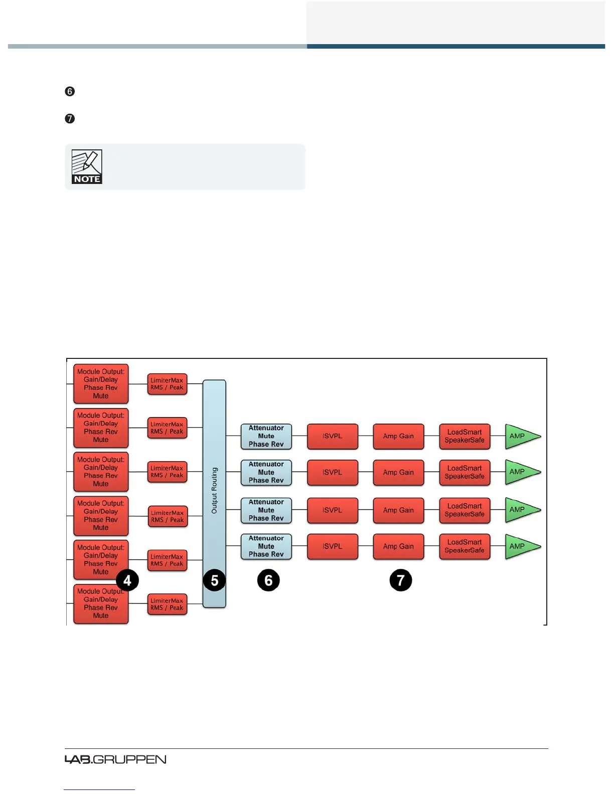
Attenuation Stage - Power output channel mute and attenuation settings
Amp Gain Stage - Amplier gain control
If the required audio signal is not passing correctly,
verify the connection, mute and volume settings at
all seven stages.
6.1.2 Power Output Section: Limiting and Sensitivity
The Current Peak Limiter (CPL) dynamically limits the drive to the power stage based on three parameters:
sensed output current level, feedback from the output stage, and sensed voltage clip from the ISVPL. This
ensures that power output is maintained within the design limits of the PLM.
The adjustable Inter-Sample Voltage Peak Limiter (ISVPL) sets the PLM’s maximum output voltage and
therefore also the maximum output power. The ISVPL setting is made via MENU > MODULE > LIMITERS
> ISVPL, and can also be set from the Lake Controller software.
Figure 6-2: Signal Flow Diagram (4-Channel PLM Part 2)
The sophisticated output section monitors faults and generates warnings when appropriate; warnings are
displayed on the front panel of the PLM and also sent as messages over the control network. In the rare
event that maximum ratings are signicantly exceeded, the PLM will shut down until the condition has
 Loading...