Front Panel Interface
39
PLM Series Operation Manual rev 1.1.9
If CPL protection is active, or a voltage clip occurs, then the associated Power Output Channel LED will ash
red and a text warning will also be displayed on the screen.
7.8.5.2 Warning or Fault Indications
If certain parameters within the PLM approach or exceed preset limits, a warning condition or fault condition
may arise. One or more LEDs provide a visual indication of the problem, along with an on-screen description
of the condition displayed adjacent to the LED/s.
▸ A green LED conrms inputs or outputs are unmuted and operating normally
▸ A yellow LED signies a warning are reserved for PLM warnings
▸ A red LED indicates a fault, clip or mute
An Event Log le lists all warnings with date and time stamps, please refer to the Lake Controller Operation
Manual for further information the Event Log.
Please refer to Table 7-2 and Table 7-3 below, and to Table 9-1 on page 72, for a detailed description of faults
and warnings.
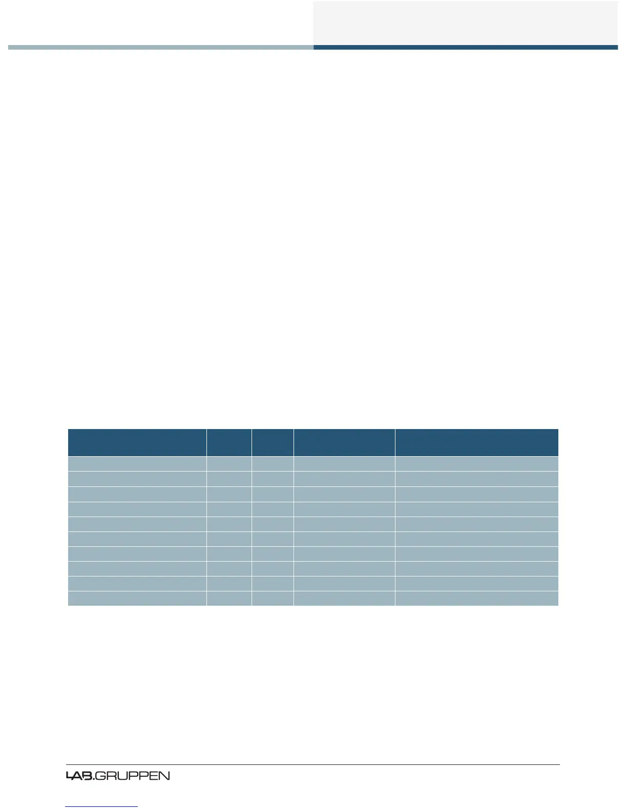
7.9 Warning and Fault Indications
Table 7-2 lists the warning conditions signied by a yellow LED;
Warning LED LED
No.
On Screen
Warning Text
Event Log Text
Power Channel Temp Warning Channel 5-8 TEMP WARN:CH Temp warning: Amp channel
Fewer Speakers Channel 5-8 UNDER SPKR CNT Under Speaker Count
More Speakers Channel 5-8 OVER SPKR CNT Over Speaker Count
Speaker Magnet Temp Warning Channel 5-8 TEMP WARN:MAG Temp Warning: Speaker Magnet
Speaker VC Temp Warning Channel 5-8 TEMP WARN:VC Temp Warning: Speaker Voice-Coil
Uncertain About Load Channel 5-8 TYPE: UNCERTAIN Uncertain About Speaker Type
Load Not Veried Channel 5-8 LOAD NOT VER LoadSmart: Load not veried
SpeakerSafe Precision Low Channel 5-8 LM PREC. LOW SpeakerSafe: Precision Low
Controller/Frame Ofine Frame 1 CTRL OFFLINE Frame Ofine
SpeakerSafe Not Started Channel 5-8 SPKSAFE INACT SpeakerSafe Not Started
Table 7-2: Warning Conditions (Yellow LED)

 Loading...