86
Application Guide
PLM Series Operation Manual rev 1.1.9
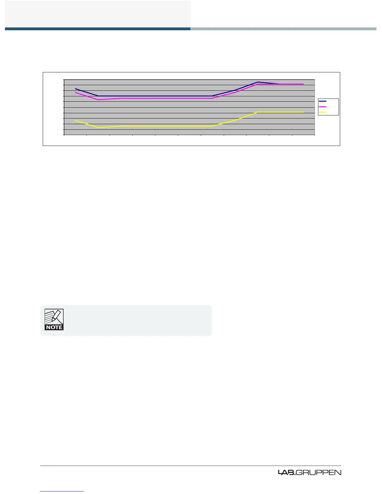
▸ Absolute Noise Floor: -71.3 dBu
-140.0
-120.0
-100.0
-80.0
-60.0
-40.0
-20.0
0.0
20.0
40.0
60.0
Analog AES Input Input Mixer Module In Module Out Amp Attenuation Analog Ref Amp Gain ISVPL Output
dB/dBu
Clip
Nominal
Noise
Figure 10-6: Analog Input: Moderate Noise with Very High Output (Very High SPL)
10.5 Speaker Congurations
Connecting two speakers in parallel to a PLM power output presents a load to the amplier which is half the
impedance of that presented by one speaker. Therefore, the current that two speakers will attempt to draw
from the output stage is double that for one speaker, and this higher current may be sufcient to cause the
Current Peak Limiter to become active. The more speakers connected to an output in parallel, the lower the
impedance and the higher the current draw.
Multiple loudspeakers may be driven by a PLM power output more satisfactorily if a series-parallel wiring
conguration is adopted. Please ensure care is taken to match polarity correctly.
When using series-parallel wiring, the nominal impedance is the same as with one speaker; however, the
principle of power sharing still applies, and it is not possible to get the amplier section to deliver more than
its rated power.
Nominal loads as low as 2 ohms are supported by the PLM.
However, a 2 ohm nominal load has impedance dips at its
resonances below 2 ohms; in such cases it is likely that the
resulting higher current will cause CPL to activate.
10.6 Digital Audio Connections
Whenever possible, it is preferable to connect a digital rather that analog input signal to the device. This is
particularly relevant if the source signal is already in the digital domain, such as the source from a digital
mixing console or digital distribution system. The primary cause of signal distortion and signal delay (latency)
is the digital-to-analog and analog-to-digital conversion process. Therefore, using digital inputs normally
provides higher quality audio with lower latency.

 Loading...