Front Panel Interface
41
PLM Series Operation Manual rev 1.1.9
7.10 Meter Mode
7.10.1 Home View
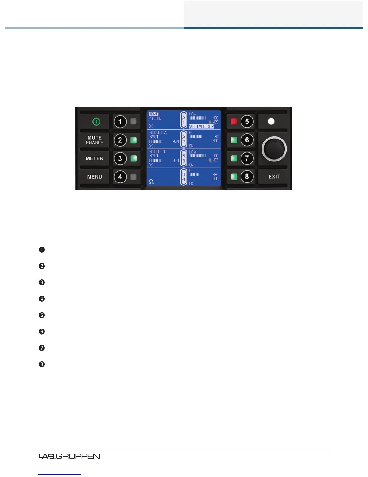
The default view when powering on the device is Meter Mode > Home View as shown in Figure 7-4.
Figure 7-4: Meter Mode > Home View
Home View provides a summary of Module I/O gain level and limiter gain reduction, along with frame,
module and channel labeling information. The example in Figure 7-4 shows a stereo 2-Way, with Module A
(Input 1) feeding power output channels 1&2, and Module B (Input 2) feeding power output channels 3&4.
Current View title & Frame label, Frame faults and warnings.
Module A label, input gain meter, faults, warnings, clips & mutes.
Module B label, input gain meter, faults, warnings, clips & mutes.
AES/EBU Terminated & Iso-Float Grounded icons (no icons = AES Unterminated / Iso-Float Floating).
Power output 1 label, gain & limiter meters, faults, warnings, clips & mutes.
Power output 2 label, gain & limiter meters, faults, warnings, clips & mutes.
Power output 3 label, gain & limiter meters, faults, warnings, clips & mutes.
Power output 4 label, gain & limiter meters, faults, warnings, clips & mutes.
Please refer to Table 7-2 and Table 7-3 on page 40 for full details on the faults and warnings that could be
displayed in any of the above locations.
 Loading...