66
Back Panel Interface
PLM Series Operation Manual rev 1.1.9
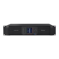
8.2.3 Unbalanced Operation
Balanced connections are recommended where possible. However, if it is necessary to drive the device
from equipment with an unbalanced output, wire the inputs as shown in Figure 8-10.
12
3
COLD
HOT
SCRN
COLD
HOT
SCRN
Unbalanced Output
(Typically phono)
Balanced Input
(XLR)
Figure 8-10: Balanced to Unbalanced Analog Wiring and Pin Out
The method shown in Figure 8-10 uses twin-and-screen (balanced) cable and standard XLR pin connections
at the PLM end, with the cold wire and the cable screen connected to the signal ground of the equipment at
the source end.
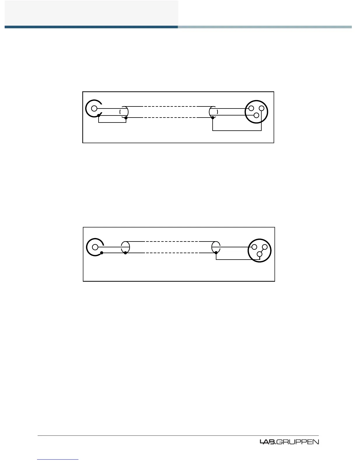
This usually provides better noise and hum rejection than the more common method of joining pins 1 and
3 together in the XLR. However, if only a single-core (unbalanced) cable is available, the method shown in
Figure 8-11 may be used.
12
3
HOT
SCRN
HOT
SCRN
Unbalanced Output
(Typically phono)
Balanced Input
(XLR)
Figure 8-11: Unbalanced Analog Wiring and Pin Out
8.2.4 Iso-Float Electronic Balancing
The analog input electronic balancing circuits use the Lake Iso-Float system.
The Iso-Float technology combines the benets of transformer-coupled isolation with the advantages of
clean, direct-coupled inputs. The audio converters are galvanically isolated, and not connected to the main
ground. High-quality transformers and opto-isolators create a barrier between the device and possible
grounding aberrations from the outside electrical environment.
Iso-Float settings are adjustable via the front panel menu or the Lake Controller software.
 Loading...