Back Panel Interface
65
PLM Series Operation Manual rev 1.1.9
8.2 Analog Inputs and Outputs
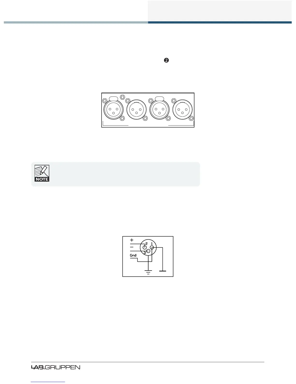
8.2.1 Analog Input and Link XLR Connections
Two electronically-balanced analog inputs are provided via latching XLR3F connections. The Link outputs on
XLR3M connectors are directly paralleled to the inputs.
INPUT 1 INPUT 2LINK
1 LINK 2
PIN 1: SCRN 2: POS 3: NEG
ANALOG WITH ISO-FLOAT
TM
Figure 8-8: Analog Input and Link XLR Connections
When linking analog inputs of several PLMs, consider that the drive capability of
the source’s output stage (e.g. mixing console) may be limited. Generally it is
inadvisable not to parallel link more than four inputs. If more links are required,
use a good quality balanced audio line driver or distribution amplier.
8.2.2 Analog & AES3 XLR Wiring and Pin Out
All XLR connections are wired to IEC268 as shown in Figure 8-9.
Figure 8-9: IEC268 XLR Wiring and Pin Out
Pin 1: Ground / Shield
Pin 2: Hot (+)
Pin 3: Cold (-)

 Loading...