64
Back Panel Interface
PLM Series Operation Manual rev 1.1.9
8.1.2 Binding Post Connectors
Binding post versions of the PLM are tted with four pairs of black and red 4 mm binding posts.
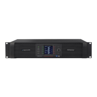
Four-channel PLMs provide the output for one power output channel on each pair of binding posts as shown
in Figure 8-6.
CH 2
CH
1
CH 4
CH 3
CLASS 2 WIRING
SPEAKER OUTPUTS
Figure 8-6: Four-channel PLM Binding Post Conguration
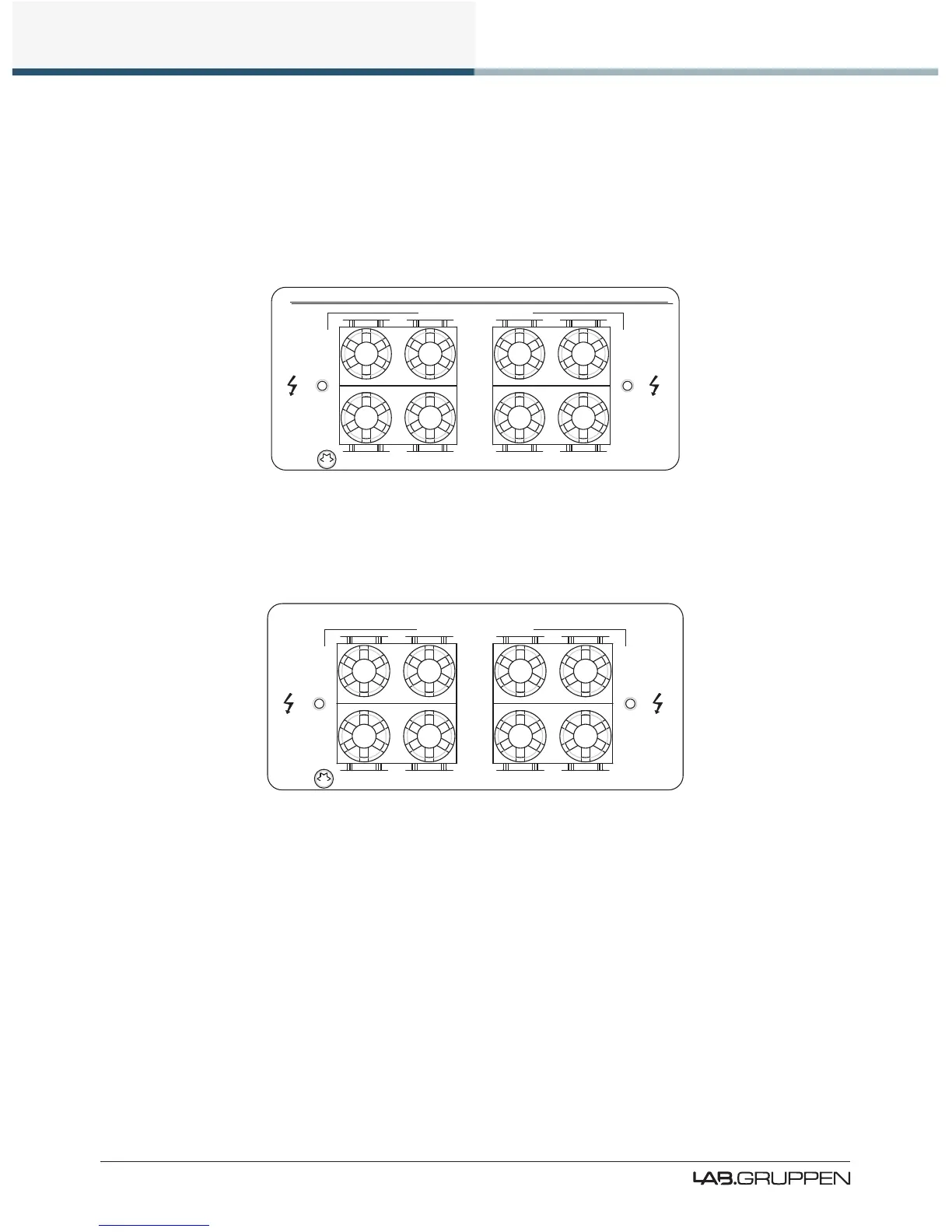
Two-channel PLMs provide each power output channel from two pairs of binding posts as shown in Figure
8-7.
SPEAKER OUTPUTS
CH 1
CH 1
CH 2
CH 2
CLASS 3 WIRING
Figure 8-7: Two-channel PLM Binding Post Conguration
Connect the ‘+’ loudspeaker terminals to the red binding posts and the ‘ – ‘ terminals to the black binding
posts. There are three methods of connecting speaker cables to the binding posts.
1. Solder 4 mm banana-plugs to the ends of the speaker wires and plug into the center of the turrets.
2. Thread the stripped ends of the wires through the holes in the posts. Enter the wires for output
channels 1 and 3 from above and for channels 2 and 4 from below. Tighten the plastic turrets by
nger only, being careful not to overtighten.
3. Crimp 4 mm insulated spade terminals onto the ends of the wires and push into the binding post
assembly from above (Ch. 1 & 3) or below (Ch. 2 & 4). The hole in the post is ignored. Hand tighten
plastic turrets, being careful not to overtighten.
 Loading...