68
Back Panel Interface
PLM Series Operation Manual rev 1.1.9
8.4 RJ45 etherCON
®
Network Connections
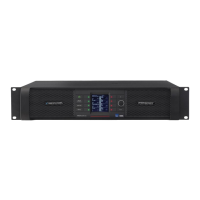
Two RJ45 etherCON style network connections are provided as shown in Figure 8-13.
SWITCHED 100/1000 Base-T
SEC LINKACT
Figure 8-13: etherCON Network Connectors
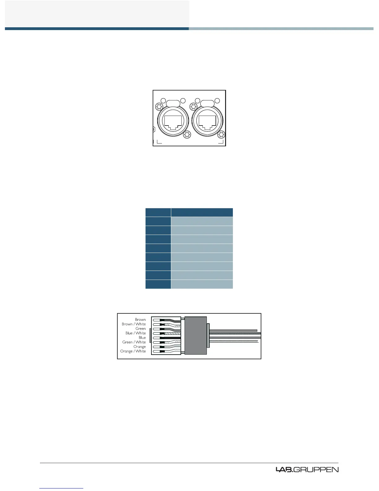
The network connections auto-sense whether standard or crossover Cat-5e cables are in use. Pre-made
cables with moulded RJ45 plugs are recommended. If it is necessary to make up custom Cat-5e network
cables, use pinout described in Table 8-3.
Pin No. Color
1 Brown
2 Brown + White
3 Green
4 Blue + White
5 Blue
6 Green + White
7 Orange
8 Orange + White
Table 8-3: RJ45 Wiring & Pin Out Description
Figure 8-14: RJ45 Wiring and Pin Out Diagram
When the device is connected to an active network, the yellow LINK LED illuminates above the connector in
use. Data activity on the network is indicated by illumination of the green ACT LED. It is normal for the ACT
LED to icker either sporadically or continuously.
 Loading...