Do you have a question about the Lab.gruppen PLM Series and is the answer not in the manual?
Read, keep, heed, and follow all safety instructions to prevent hazards.
Warnings regarding rain, moisture, liquids, earthing connection, and plug accessibility.
Caution against removing screws and user-serviceable parts.
Covers grounding, speaker output hazards, speaker damage, and maintenance responsibilities.
Apparatus must be connected to a grounded socket outlet.
Warnings about hazardous output voltages and connecting/disconnecting cables.
Information on potential loudspeaker damage from overpowering.
Details on FP+ Series amplifier platform, power density, Class TD stages, and cooling.
Inter-Sample Voltage Peak Limiter tailors output to load characteristics.
Proprietary DSP tools for load verification and real-time performance monitoring.
Integration with Lake Processing, programmable crossovers, EQ, and limiting.
Dante digital audio networking over Ethernet for simplified configuration and low latency.
Guidelines for airflow, rack space, and specific rear mounting options.
Explains forced-air cooling system, airflow direction, and temperature sensing.
How the system protects against overheating and the importance of dust filters.
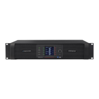
Overview of front panel controls: LCD, function buttons, rotary encoder.
Overview of the back panel layout for 4-channel and 2-channel PLM models.
Details on Analog Inputs, Analog Links, AES/EBU Inputs, and AES/EBU Link.
Description of XLR3F connectors for electronically balanced analog inputs.
XLR3F connector for AES/EBU digital audio signal.
Information on binding posts or Neutrik Speakon connectors for power outputs.
Details on RJ45 etherCON network connections and mains power connector.
RJ45 etherCON for Ethernet control network and Dante digital audio.
Neutrik powerCON connector for AC mains input.
Precautions before making connections, AC voltage check, and powering on.
Details on Class TD technology, efficiency, and load conditions.
Table showing symmetrical load power ratings for different models.
Table showing asymmetrical load power ratings for different models.
Overview of protection circuits and indications via LEDs and software.
Explains ISVPL as a voltage limiter and its operating principles.
Describes Universal and Sub/LF profiles for ISVPL limiting.
CPL ensures output transistors stay within Safe Operating Area (SOA).
PAL controls AC current to power supply to prevent PSU overload.
BEL models external breaker temperature and limits mains current.
UVL reduces mains current draw when voltage drops below a threshold.
CAL monitors RMS current to protect power output stages from overload.
VCL acts to prevent clipping on subsequent peaks when PSU regulation is exceeded.
Describes temperature sensing system protecting against overheating.
Details on temperature monitoring and fault indication.
Indicates power output channel temperature warnings/faults via LEDs.
Indicates PSU or DSP area overheating via red LED and message.
Prevents damage to loudspeakers or components from DC at the output.
Protects against Very High Frequency content in the input signal.
Detects low impedance or short circuit at output terminals, mutes output.
Details on R.SMPS, power factor correction, and universal power supply.
Depicts audio signal flow and adjustment points within a PLM.
Explains Current Peak Limiter (CPL) and ISVPL for output management.
Integration with Lake Processing, programmable crossovers, EQ, dynamics.
Control and monitoring via LCD, function buttons, and rotary encoder.
Visual indications of faults/warnings via LEDs and LCD.
Details on LCD, dynamic buttons, controls, and LEDs.
Used for parameter adjustment and changing meter views.
Overview of PLM mute functions (Input, Module Input/Output, Power Output).
Tricolor LEDs convey status: faults, warnings, clip, mutes.
Monitors input and output clip conditions.
Details yellow LED for warnings and red LED for faults.
Adjusting ISVPL Threshold, ISVPL Profile, MaxPeak, and MaxRMS levels.
Available output connectors: binding posts or Neutrik Speakon.
Details on analog input and link XLR connections.
Details on AES3 XLR connector and connections.
Two RJ45 etherCON connections for network connectivity.
Overview of fault/warning indications via LED and LCD.
Overview of gain adjustments in the signal path.
Maximizing volume capability and minimizing noise.
Lists specifications for PLM 20000Q, PLM 14000, PLM 10000Q.
General warranty terms, coverage, and exclusions.
How to obtain technical assistance and service.
Instructions for factory service, product return, and contact info.
| DSP | Yes |
|---|---|
| Network | Ethernet |
| Connectors | XLR, SpeakON |
| Cooling | Forced air |
| Protection Features | Overheat, DC, short circuit |
| Control Software | Lake Controller |