42
Front Panel Interface
PLM Series Operation Manual rev 1.1.9
Output limiter (gain reduction) meters take
into account the sum of PLM ISVPL and Lake
LimiterMax.
Home View looks similar for most congurations, with slight variations dependant on the PLM model and
processor conguration, for instance:
▸ A four-channel PLM with a Classic 4-Way routed to all four power output channels will not have any
information in block
as Module B is not in use by this PLM.
▸ A two-channel PLM with a Classic 2-Way routed to both power output channels will not display data in
, or . This is because Module B is not in use and the output channels are displayed using .
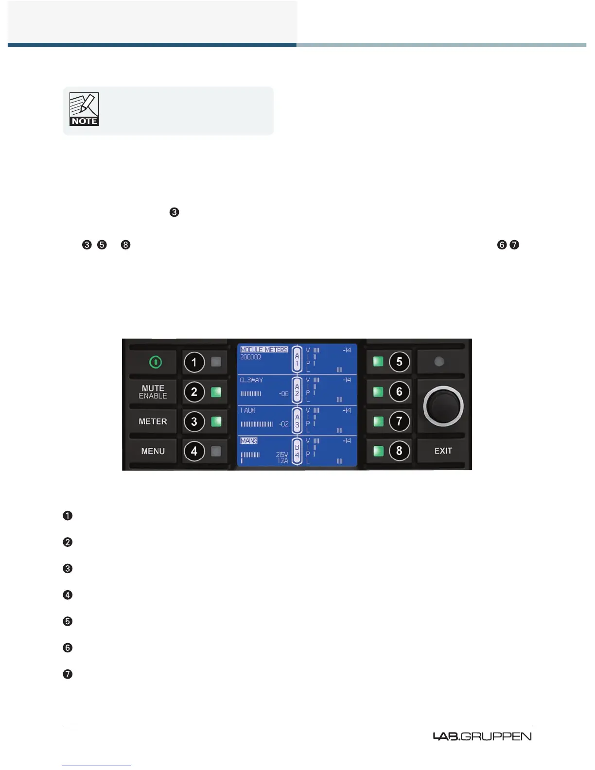
7.10.2 Module View
Module View provides further signal level information in the form of additional power output meters as
shown in Figure 7-5.
Figure 7-5: Meter Mode > Module View
Current View title & Frame label, Frame faults and warnings
Module A label and input gain meter
Module B label and input gain meter
Main Voltage and Ampere Meter (PLM 20000Q ONLY)
Output 1: V - Voltage Meter I - Current Meter P - Power Meter L - Gain Reduction Meter
Output 2: V - Voltage Meter I - Current Meter P - Power Meter L - Gain Reduction Meter
Output 3: V - Voltage Meter I - Current Meter P - Power Meter L - Gain Reduction Meter
 Loading...