38
Front Panel Interface
PLM Series Operation Manual rev 1.1.9
Fault condition LED indications take priority
over mute status indications. If a fault
condition occurs, the LED will indicate the
fault and not the mute status.
7.8.5 LED Fault, Warning and Clip Indication
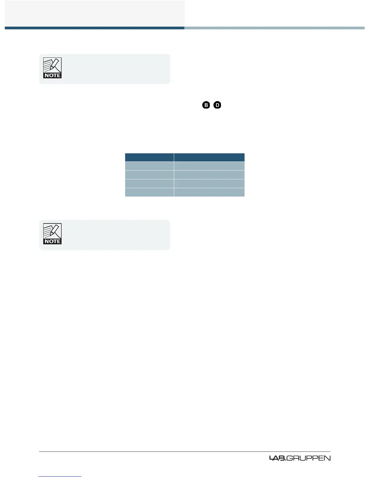
A tricolor LED is embedded inside each of the eight dynamic function buttons. These convey a variety of
status indications including faults and warnings, signal clip indications, Module input mute, Module output
mute and Power Output mute. Table 7-1 summarizes the meaning of the LED indications.
LED Color Indication
Green Status Good / Unmuted
Yellow Warning
Red Fault / Muted
Flashing Red Clip
Table 7-1: LED Fault and Warning Indications
An unlit output LED indicates either the
channel is not available for the model in use,
or that the power output channel is not
routed to a Module output channel.
7.8.5.1 Clip Indication
The front panel LEDs also indicate input and output clip or pre-clip conditions that can occur within the PLM.
Input Clip
Input clipping is monitored at two stages in the signal path:
▸ Analog Input Stage: If the input signal exceeds either +12 dBu or +26 dBu (according to analog sensitiv-
ity setting), a clip indication is displayed. Not applicable for AES or Dante inputs.
▸ Module Input Stage: If the signal level at this point exceeds +25 dBu, a clip indication is displayed.
Input clipping is indicated the affected Module LED ashing red and INPUT CLIP displayed on the LCD.
If a subsequent input clip within 400 ms is detected, the LED remain lit for a longer period.
Output Clip
All output channels are monitored by a suite of protection circuits that include a Current Peak Limiter (CPL)
and an Inter-Sample Voltage Peak Limiter (ISVPL). Please refer to section 5.3 for further information.

 Loading...