84
Application Guide
PLM Series Operation Manual rev 1.1.9
-250,0
-200,0
-150,0
-100,0
-50,0
0,0
50,0
100,0
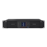
Analog AES Input Input Mixer Module In Module Out Amp Attenuation Analog Ref Amp Gain ISVPL Output
dB/dBu
Clip
Nominal
Noise
Figure 10-2: Digital Input: Low Noise with Good Headroom (High Input / High SPL)
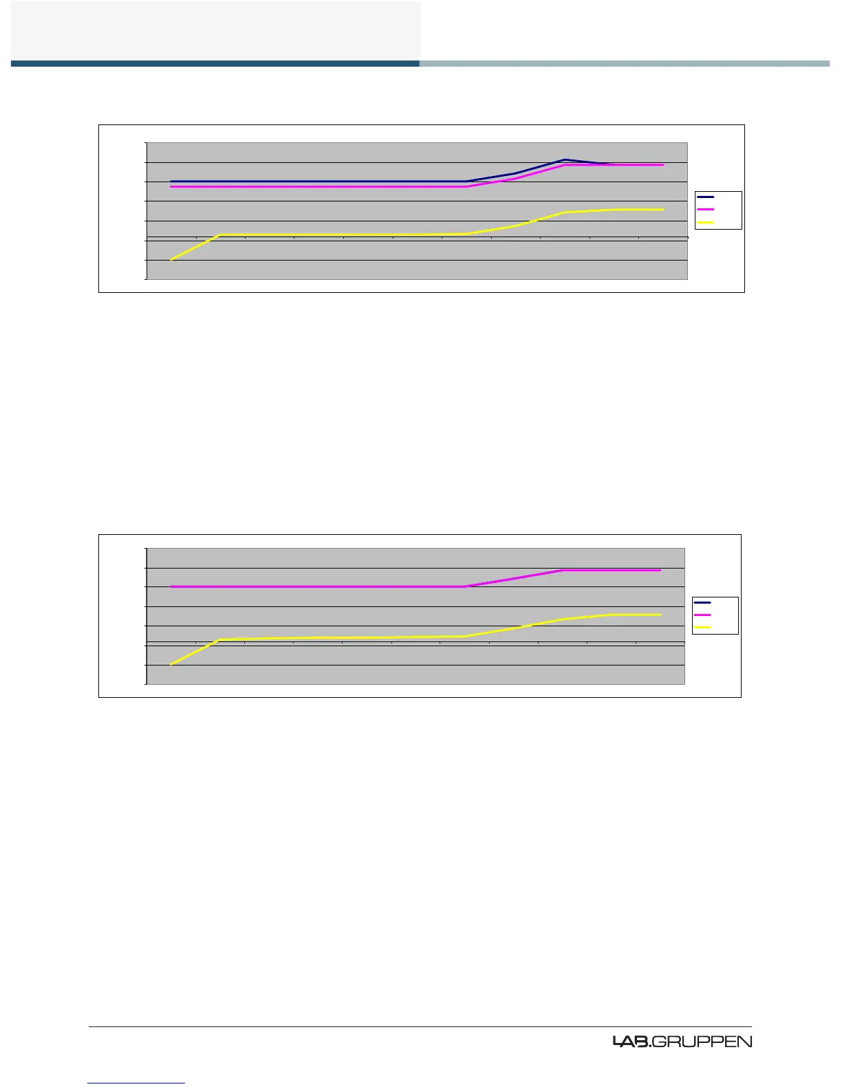
Figure 10-3 illustrates how to achieve the lowest possible output noise, although this is not a recommended
conguration.
▸ Input Clip: 0 dBFS
▸ Amp Gain: 22 dB
▸ SNR: 114.8 dB
▸ Absolute Noise Floor: -71.9 dBu
-250,0
-200,0
-150,0
-100,0
-50,0
0,0
50,0
100,0
Analog AES Input Input Mixer Module In Module Out Amp Attenuation Analog Ref Amp Gain ISVPL Output
dB/dBu
Clip
Nominal
Noise
Figure 10-3: Digital Input Optimized for Minimum Noise - Not Recommended
The improvement in noise performance (at the cost of losing headroom and compression features) is only
0.6 dB; it is therefore not recommended to optimize performance in this manner.
10.4.3.2 Analog Input Gain Structure Examples
Figure 10-4 illustrates how to minimize absolute noise while limiting the available SPL.
Input Clip: 12 dBu
▸ Amp Gain: 22 dB
▸ SNR: 105.5 dB
 Loading...