It is very important to take voltage drop across the system network into consideration when planning an installation. It is
the cable resistance on the power supply wiring that gives rise to voltage drop - the longer the cable run and the larger
the current requirement, the larger the voltage drop. To perform a detailed assessment of voltage drop is complex; you
need to know the current requirement of each device, the distance between each device and the resistance of the cable
per metre. To estimate the worst case scenario simply take the maximum cable run and calculate the voltage drop as if all
devices were at the end of the cable.
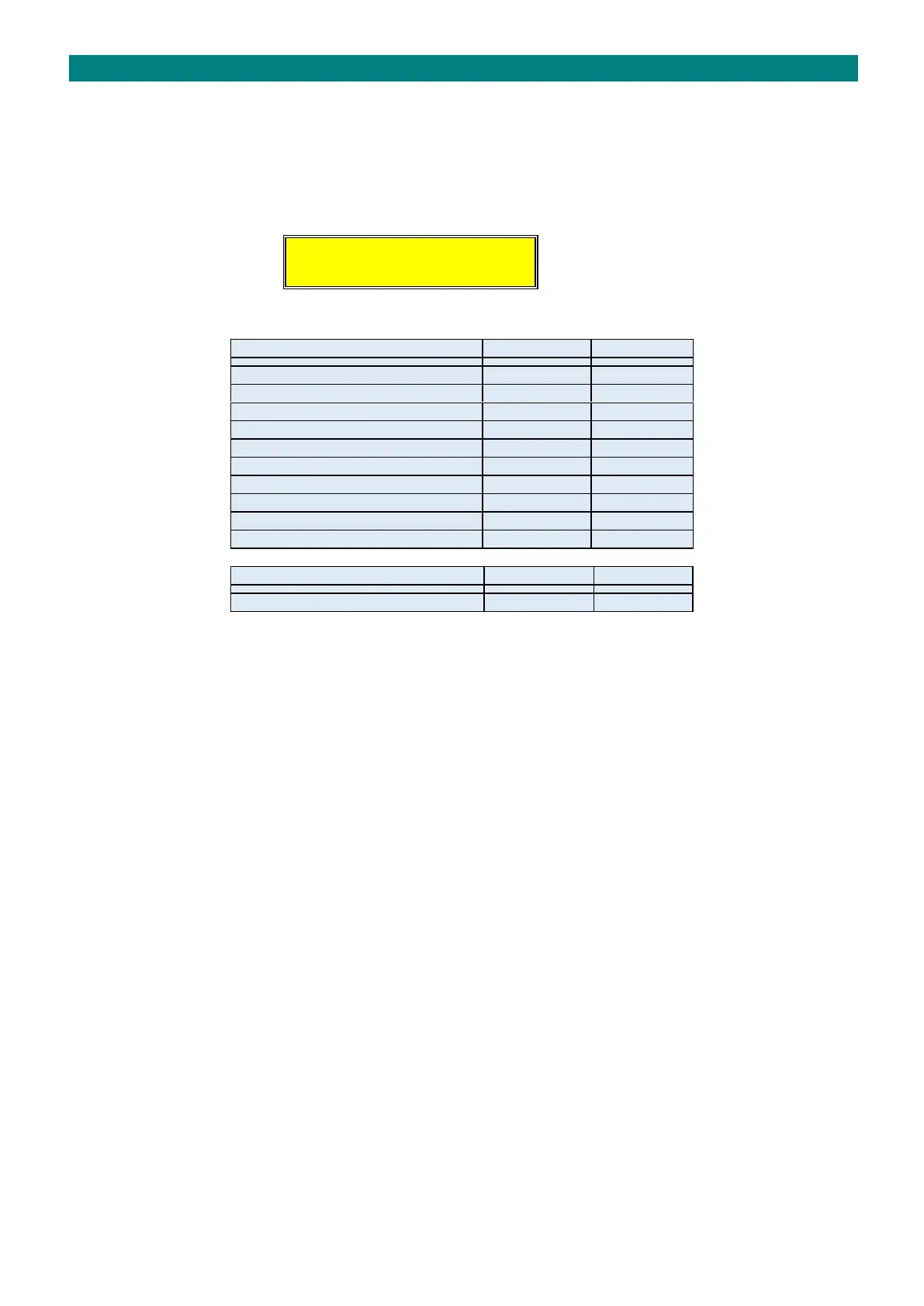
Typical current requirements of devices connected to the Advent xt network are given below:
EXAMPLE
The estimated voltage drop on an installation with 40 intercoms, 1 status module, 1 manager callpoint, 1 lift callpoint and
6 network receivers on 400 metres of cable would be;
(40 x 2mA) + (1 x 12mA) + (2 x 2mA) + (6 x 10mA) = total current 156mA (0.156A) on 24V line
400 metres of CW1308 cable = 40Ω (10Ω per 100 metres)
using V = I x R: 0.156A x 40Ω = 6.24V drop on 24V line (leaving approx. 18V)
Devices on the 24V supply will work down to approx. 16V therefore the above drop is acceptable.
REDUCING VOLTAGE DROP
There are several means of reducing the voltage drop; site conditions will dictate which is used;
1. The best solution is to split the network into a number of short spurs rather than one long run. This has the advantage
of smaller voltage drops per cable run and simplified fault finding.
2. On large installations install a 1.0mm power pair or a CW1308 with additional spare pairs to allow “doubling-up” on
power conductors. Increasing the cable cross section area will reduce its resistance therefore reducing the amount of
voltage dropped.
3. Looping back the power conductors from the last intercom to the controller will form a ring circuit which will effectively
halve the resistance.
4. An auxiliary power supply can be connected to the site wiring at a suitable point to “jack-up” the supply midway along
the cable run. The disadvantage of this being future service engineers may not be aware of PSU’s presence and the
network will remain powered when the controller is switched off.