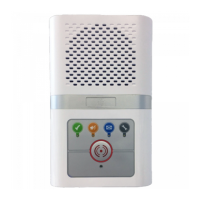
The Manager Callpoint (P/No. ZXT250) is an external
speech unit used to initiate a call from outside the building.
It is connected to the system network similar to a standard intercom.
INSTALLATION
The standard backbox is designed for flush mounting - a surface mount backbox (P/No. HM0821) or a stainless surface
cowling (P/No. HM1125) is available separately. Do not cut a hole in the top face of the backbox for cable entry as this
may allow water to enter and damage the electronic components. The cut-out dimensions given below will allow the
backbox to fit flush into the wall or door screen with the bezel overlapping by approx. 14mm on all sides.
The backbox should be sealed with suitable mastic to prevent water ingress. All backboxes must be earth bonded in line
with current IEE regulations. The fascia is fixed by 4 off M5x12mm Allen key screws which require a 3mm Allen key tool.
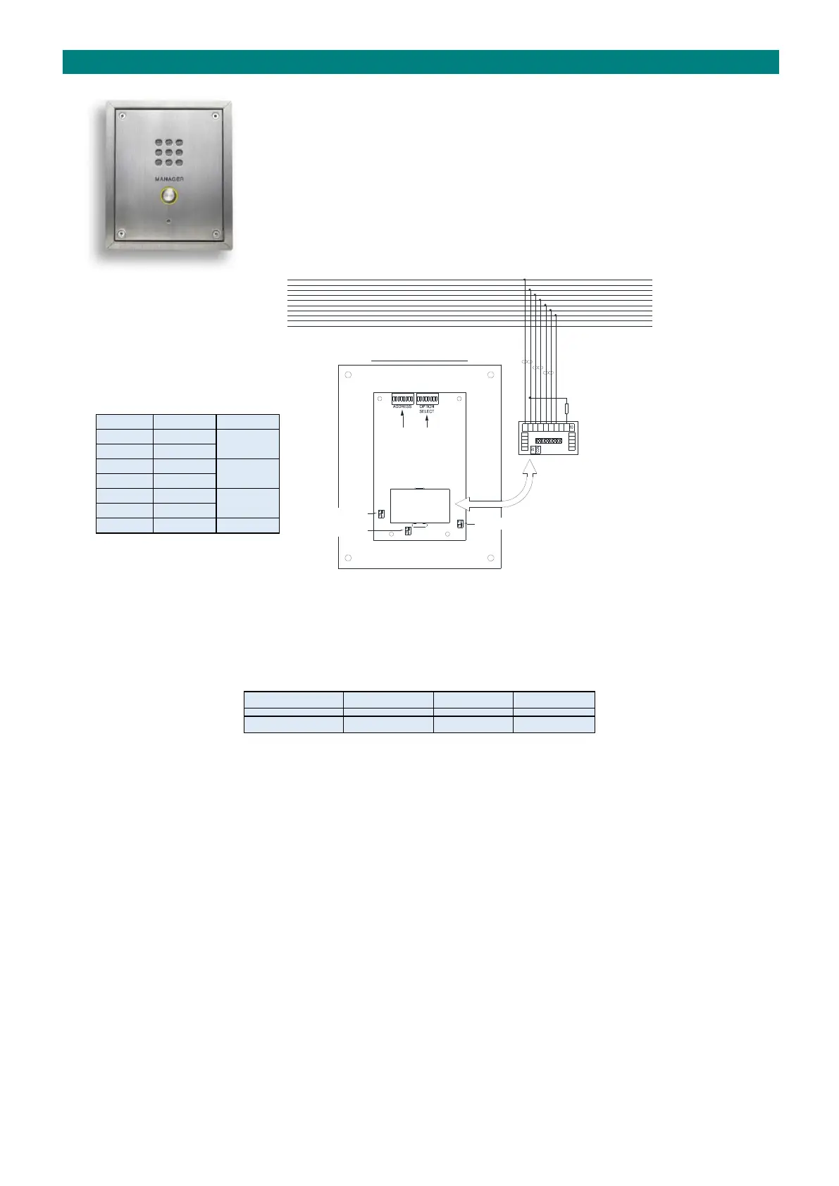
TERMINATION
Carefully unplug the termination board off the back of the Manager Callpoint to gain access to the screw terminals.
Connect to the system network wiring as shown above, fit a 4K7 resistor across terminals 2 & 9 to prevent an “open
circuit fault” being reported, and then refit the termination board ensuring correct orientation. Note; there is no PA
facility on a Manager Callpoint.
DIL SWITCHES & LINKS
The “OPTION SELECT” DIL switch should be set all OFF and the “ADDRESS” DIL switch should be set with the next available
unique 8 bit binary address. Fit Links LK1 in position “B” & LK2/LK3 in position “A”.
DOOR LOCK CONNECTION
The N/O clean contact output on terminals 16&17 can be used to release an electric lock. Power for the lock release must
be taken from an additional PSU - not the Advent xt network. Alternatively, an auxiliary relay output on the Advent xt
controller can be programmed to activate with any DTMF character - see the Advent xt Programming Manual (Tynetec
Doc No. FM0411).