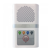
The intercom unit should be wall mounted in a central location within each dwelling. Screw fix the intercom rear securely
to the wall using the 4 holes marked “A”. The 2 holes marked “B” can be used for an embedded box. Ensure the case is
not twisted as this may prevent the lid fitting correctly.
97mm
70mm
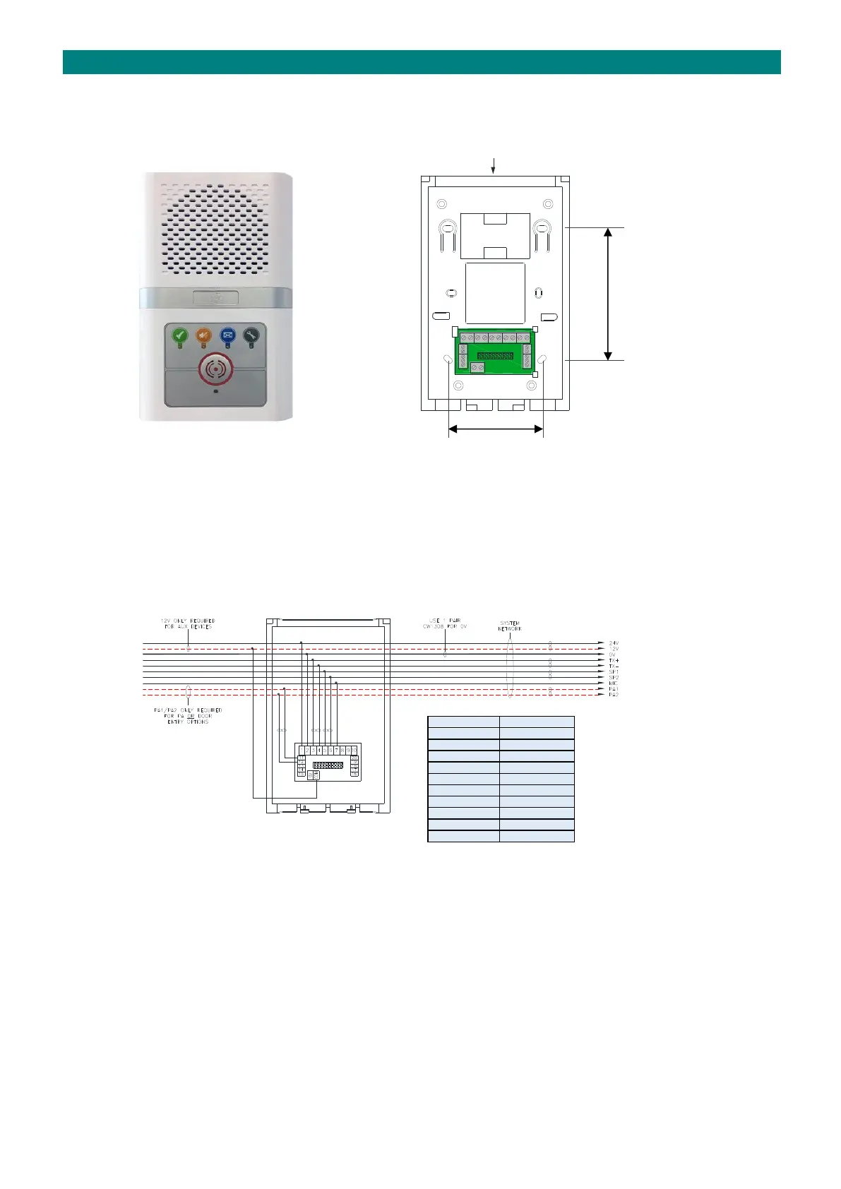
The network cable should loop-in and out of each intercom via the cable entry channel on the top or the square cut-out in
the rear. Wherever possible avoid cable entry from below as this may interfere with the operation of the emergency
pullcord. The cable clips marked “C” can be used to retain spare cores and prevent possible short circuits when the
intercom front is fitted.
INTERCOM TERMINATION
The network wiring is terminated on the interconnect board in the rear section of the intercom as shown below;
NETWORK NETWORK
WIRING ➔ ➔ WIRING
IN OUT
The 12V connection (COM) is only necessary if there are auxiliary devices within the dwelling that require a 12V DC
supply. Likewise, the PA1/PA2 connection is only necessary for the public address option or if door entry telephones are
fitted. If all cores are available in the network cable it is good practice to make all the connections for possible future
upgrades.