Doc No. FM0410 issue N Page 34
25. DIGITAL DOOR PANEL INSTALLATION
TERMINATION
See Tynetec Drg No. ZXT100 sheet 3 for detailed wiring connections;
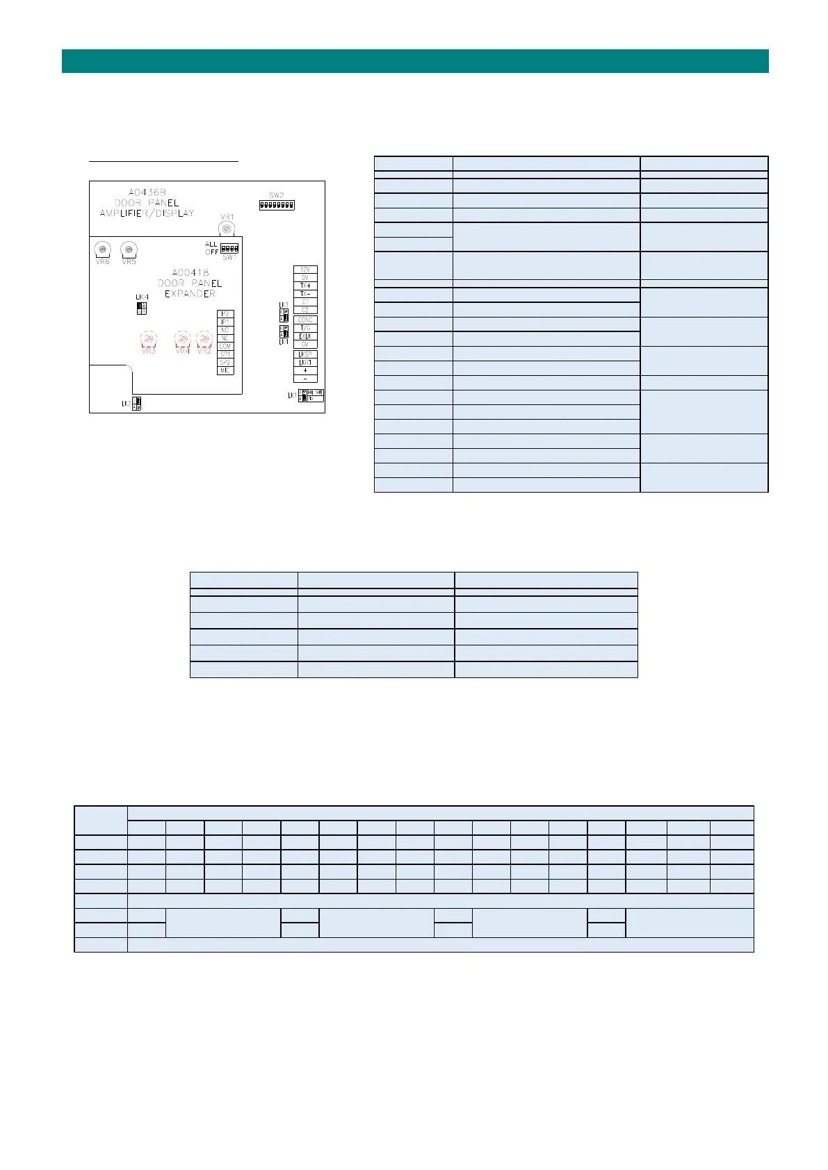
DOOR PANEL AMPLIFIER BOARD
LINK SETTINGS
LK1 selects a standard or fail safe lock type; a standard lock requires power to unlock (fail-secure) whereas a fail-safe lock
requires power to lock (fail open). See below for other link settings.
The lock release duration is set in the “Door Entry Setup” programming; see the Advent xt Programming Manual (Tynetec
Doc No. FM0411).
8 WAY DIL SWITCH SETTINGS (SW2)
DIL switches 1 to 4 are used to set a unique door panel ID (1 to 16). Door panel ID’s must start from 1 and run
sequentially. DIL switches 5 to 8 select the door panel features should all be ON for Advent xt.
ON for Digital Door Panel - OFF for Functional Door Panel
OFF = No Expander - ON = Expander Board Fitted
4 WAY DIL SWITCH SETTINGS (SW1)
DIL switches 1 to 4 are normally all OFF. Set DIL Switch 1 ON to disable the voice reassurance and revert to standard
reassurance tones. DIL switches 3 to 4 have no function.
Activates for duration of call
Warden Call Loudspeaker Audio
1 pair CW1308 to
Advent xt Controller
Warden Call Microphone Audio
1 wire CW1308 to
Advent xt Controller
12V DC Supply for Door Panel
2 pairs CW1308 to
Advent xt Controller
1 pair CW1308 to
Advent xt Controller
1 pair CW1308 to
Advent xt Controller
Door Entry Audio to Phone
2 pairs CW1308 to
PTE & Door Contact
External Lock input (N/O)
Common for T/G & EXLK inputs
1.0 mm pair to local
Lock PSU