Doc No. FM0410 issue N Page 35
25. DIGITAL DOOR PANEL INSTALLATION
PROGRAMMING
The number of door panels, Access Codes, Trade Times and Call Transfer Times must be set in the “Door Entry Setup”
programming - see the Advent xt Programming Manual (Tynetec Doc No. FM0411).
VOLUME ADJUSTMENT
The 5 potentiometers VR2 - VR6 in each door panel are used to independently adjust the audio level to/from the door
entry and warden call system. To reduce feedback the door panel microphone gain is automatically muted when the
person in the flat (or the warden) speaks - the speed at which this mute is applied can be adjusted using the VOX
sensitivity pot (VR4).
audio to door entry phone
audio to door panel (from door entry phone)
door panel VOX sensitivity adjustment
wardens audio to door & voice messages
All adjustments should be made carefully to achieve optimum volume without feedback or echo. Call a door entry
telephone via the digital keypad and adjust VR2/VR3/VR4. Press the “Manager” button to call the warden and adjust
VR5/VR6. As adjustments are made, temporarily replace the panel in the backbox whilst performing the test call.
LCD CONTRAST
The potentiometer VR1 on the door panel board is used to adjust the LCD contrast.
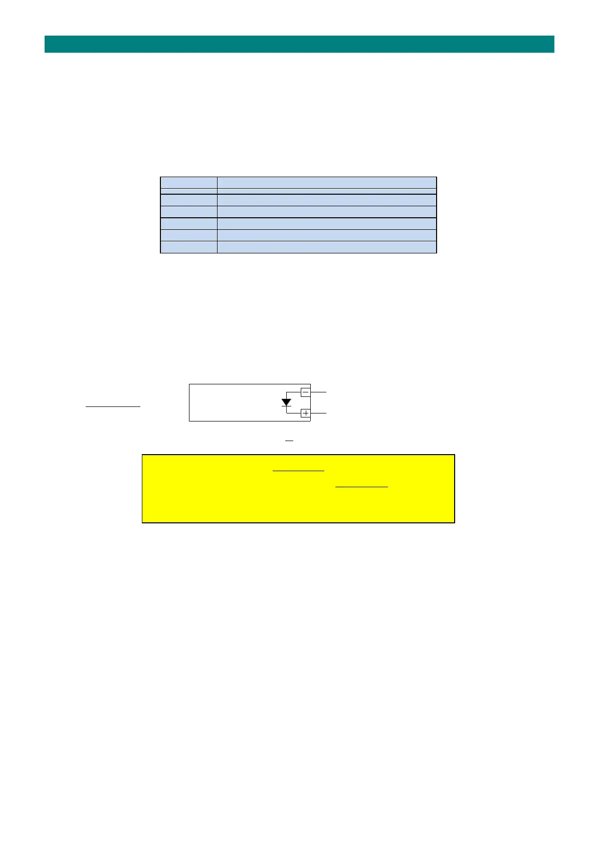
LOCK CONNECTION
The lock release is connected directly to the door panel lock supply (LKSP) and lock return (LKRT) terminals using at least
1.0mm diameter cable.
DOOR PANEL “LKRT”
DC LOCK ONLY
DOOR PANEL “LKSP”
Diode Type: 1N4001 or MOV Type: GNR07D330K
IMPORTANT
An MOV or reverse bias diode must be fitted directly across all DC lock
terminals to prevent back e.m.f. from the lock coil causing malfunction
and possible long term damage to the door panel or controller.
EXLK CONNECTION
A “press to exit” (PTE) button is used to override the lock and allow egress from the building. The PTE button should be
momentary action with both N/O and N/C contacts. The N/O contacts are connected across 0V & EXLK in the door panel
to provide a fixed 10 second timed lock release. With constantly energised locks it is recommended that the N/C contacts
are also connected in series with the lock supply to provide fail safe operation of the lock.
T/G CONNECTION
A N/C door contact can be connected across 0V & T/G in the door panel to detect when the entrance door is opened.
When the contacts open the lock time is curtailed to reduce the likelihood of other visitors entering during the same lock
release period (ie. tailgating). The telephone “door open” LED’s will illuminate green when the door is open if enabled in
the “Door Entry Setup” programming. If a door contact is not fitted then the T/G terminal must be linked to 0V.