Doc No. FM0410 issue N Page 29
LK1
LK2
ON
1 2 3 4 5 6 7 8
RESET
23. NETWORK RECEIVER INSTALLATION
Up to 16 x 169MHz Network Receivers (P/No. ZXT325) can be installed throughout a site to provide radio coverage for
personal pendants or other Altec radio devices.
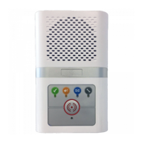
BNC CONNECTOR FOR AERIAL
ABS ENCLOSURE 160x80x55mm
SET UNIT ADDRESS DIL SWITCH ➔ LK1 & LK2 LINK SETTINGS
ADVENT xt NETWORK CONNECTION
USE 2 PAIR CW1308 (POWER & DATA)
CONNECTION
Network Receivers require a power and data connection from the Advent xt system network using a 2 pair CW1308 cable.
LINK SETTINGS & SOFTWARE VERSIONS
From September 2011 Network Receivers have 2 PCB link options LK1 & LK2. These are factory set to match the firmware
version and model of Receiver.
169MHz Zoned Network Receiver
INSTALLATION
Network Receivers should be sited in a dry secure area; they are NOT suitable for outdoor locations.
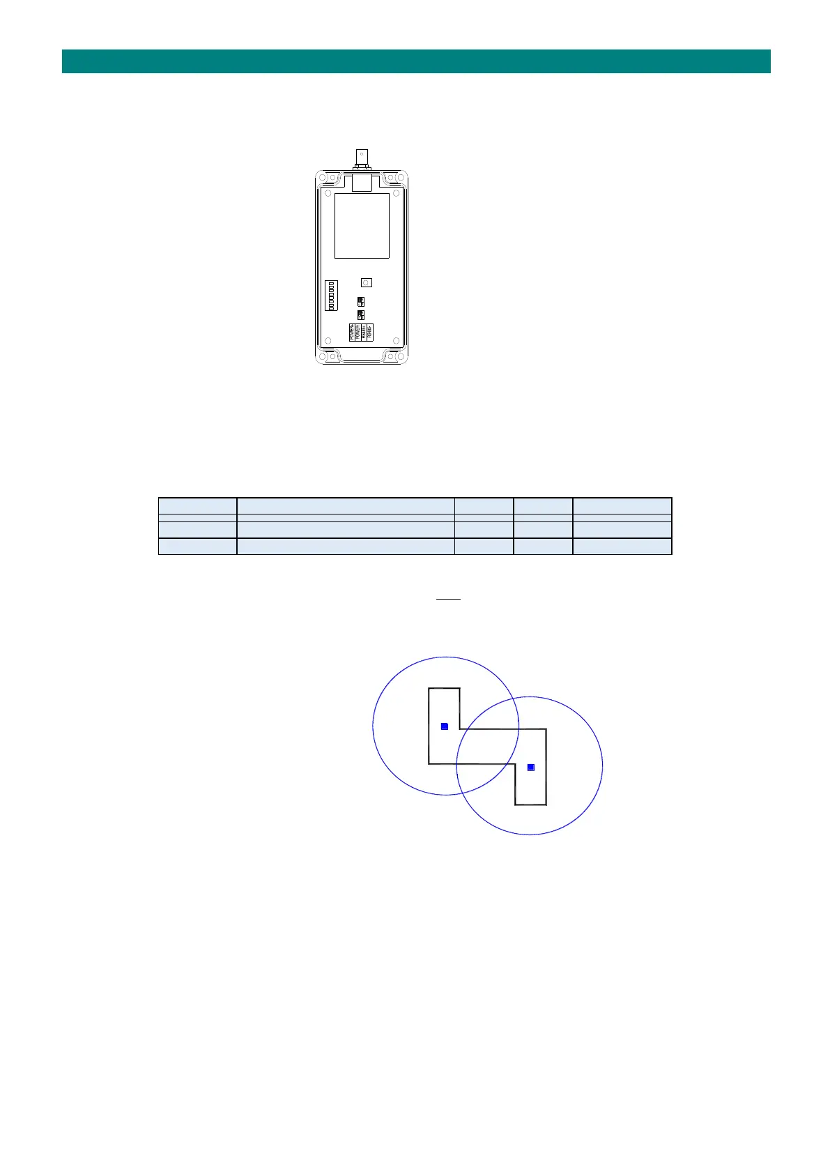
As the fabric and layout of all buildings differ, an RF site survey is recommended for each installation to establish the best
locations. A typical radio range of 75 metres radius can be expected for a Network Receiver with a 1/2 Wave Aerial, see
building plan below with 2 receivers giving full coverage;
Construction materials such as foil backed plasterboard, reinforced concrete or stone walls will reduce range.
Environmental conditions such as high levels of transmission at nearby frequencies or emissions from other electrical
equipment may further reduce range. Clear line-of-sight will give best range.
Network Receivers
with 1/2 Wave Aerials
give approx. 75m
radius radio coverage