Doc No. FM0410 issue N Page 15
10. NETWORK TERMINATION BOARD
PA & DOOR ENTRY
The optional PA amplifier and/or door entry panels are connected to the termination board;
Enable signal connected to PA amplifier board
DECT audio connected to PA amplifier input
RS485 bi-directional data bus
PA audio signal (100V line) from PA amp output
See Tynetec wiring diagram Drg No. ZXT100 sheet 2.
SYSTEM NETWORK
There are 3 blocks of pluggable XT network terminals - if there are more than 3 legs simply connect in parallel in any
block. The terminals on the system network have the following functions;
24V DC supply for network devices - fused at 1.6A
12V DC supply for auxiliary devices - fused at 1.6A
RS485 bi-directional databus
C1 = door entry audio to door
C2 = door entry audio to phone
On systems with public address and door entry telephones the PA1/PA2 pair is shared for PA audio or door entry C1/C2
audio depending on mode of operation.
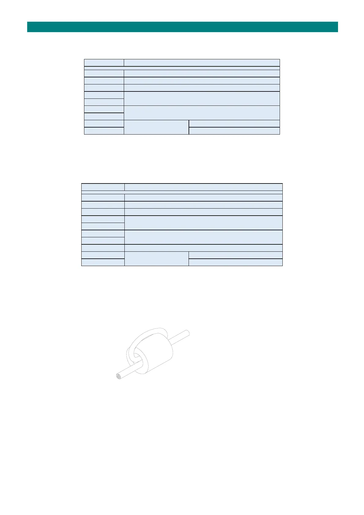
FERRITE CORE
The network wiring should be looped through a ferrite core before being connected to the termination board. This will
suppress any voltage transients induced on the network wiring and greatly reduce the likelihood of damage to the main
CPU board.
NETWORK CABLE
LOOP NETWORK CABLE THROUGH THE
FERRITE CORE BEFORE CONNECTING
TO THE ADVENT xt TERMINATION BOARD
TO TERMINATION BOARD ➔
Four ferrite cores are provided in the kit of parts with the Advent xt controller - for additional ferrite cores order Tynetec
P/No. T06050.