Zoned Network Receivers help the onsite Manager to identify which area of the building
a pendant alarm has come from.
169MHz Zoned Network Receivers were introduced in September 2011 and can only be
used with Advent xt Controller firmware V2.03a onwards.
Full radio coverage must first be achieved using standard ZXT325 Network Receivers
with W06250 1/2 Wave Aerials, then a limited number of ZXT326 Zoned Network
Receivers can be deployed around the site to give localised radio coverage.
IMPORTANT: the maximum number of Zoned Network Receivers per site is 12, for
example you could install the following maximum combinations; 4 standard + 12 zoned,
or 6 standard + 10 zoned, or 8 standard + 8 zoned etc.
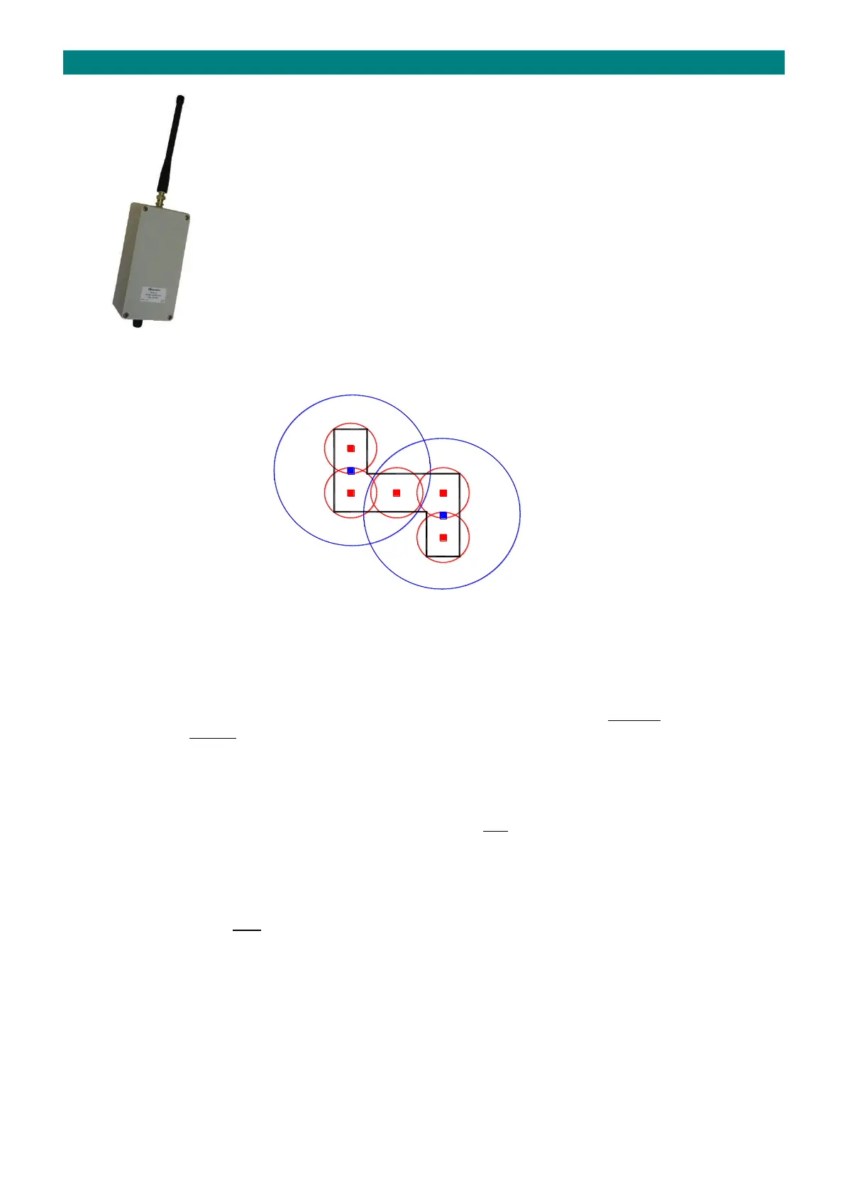
The building plan below shows two ◼ Standard Network Receivers giving approx. 75 metres radius radio coverage and
five ◼ Zoned Network Receivers giving approx. 20 metres radius radio coverage;
When a pendant is activated the zone with the strongest Radio Signal Strength (RSSI) will be identified in the alarm
message. If the pendant is not within range of any Zoned Receiver then the call will still be picked-up by the Standard
Receivers and reported without any zone information.
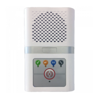
ATTENUATOR & AERIAL
To give the reduced range, Zoned Network Receivers are supplied with a 10dB BNC Attenuator and a Helical Stub Aerial.
Simply plug the BNC Attenuator between the Network Receiver and the Aerial. These 2 parts MUST BE fitted to Zoned
Network Receivers - DO NOT fit 1/2 Wave Aerials (W06250).
CONNECTION
Zoned Network Receivers require a power and data from the Advent xt system network using a 2 pair CW1308 cable.
INSTALLATION
Zoned Network Receivers should be sited in a dry secure area, they are NOT suitable for outdoor locations. Choose
locations central to the zone you intend covering. Try and space the Receivers to minimise radio overlap between
neighbouring zones. See the following page for details of testing and RSSI attenuation.
ID SETTING
DIL switches 1 to 4 are used to set a unique ID on each Zoned Network Receiver, DIL switches 5 to 8 are not used. ID’s
must follow on sequentially after the Standard Network Receivers. See table on previous page.
PROGRAMMING
The ID’s of the Zoned Network Receivers must be set in the “Zoning Setup” programming.
The total number of Standard + Zoned Network Receivers must be set in the “General Setup”.
See the Advent xt Programming Manual (Tynetec Doc No. FM0411 issue “F” onwards).