Step
Perform on each controller module
1
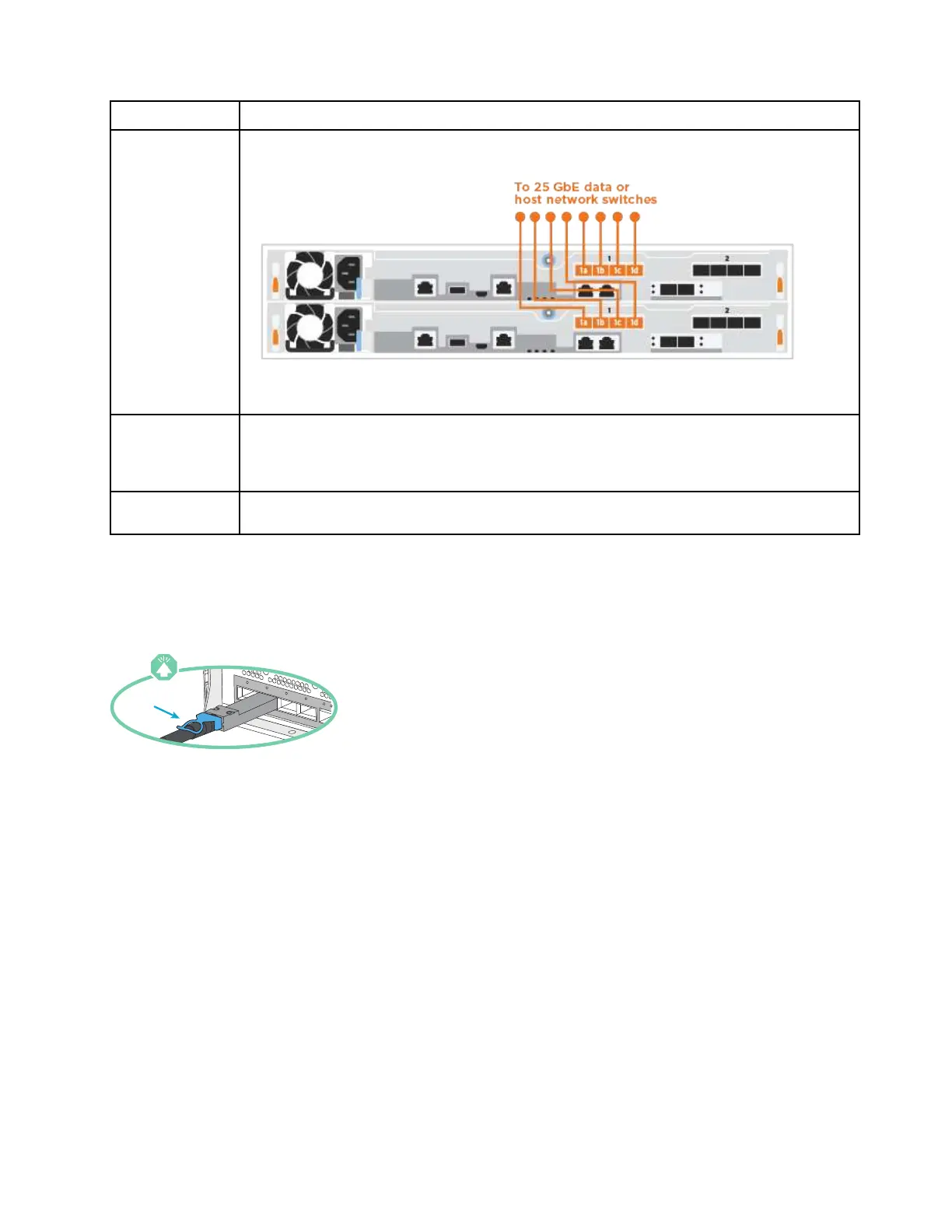
Cable ports e1a through e1d to the 10GbE host network switches.
2 To perform other optional cabling, choose from:
•
“Cabling to a Fibre Channel host network” on page 17
• “Cabling the controllers to a single drive shelf” on page 19
3
To complete setting up your system, see
“Completing system setup and configuration” on page
20
.
Cabling the controllers to a single drive shelf
You must cable each controller to the NSM modules on the DM240N drive shelf.
Be sure to check the illustration arrow for the proper cable connector pull-tab orientation.
Note: As you insert the connector, you should feel it click into place; if you do not feel it click, remove it, turn
it around and try again.
Step 1. You can use the step-by-step instructions to cable your controller modules to a single shelf.
1. Cable e1a on controller 1 to the e0a on NSM A on the DM240N.
2. Cable e1b on controller 1 to the e0b on NSM B on the DM240N.
3. Cable e1a on controller 2 to the e0a on NSM B on the DM240N.
4. Cable e1b on controller 2 to the e0b on NSM A on the DM240N.
Chapter 3. System installation and setup 19
 Loading...