• Power off the server and disconnect all power cords for this task.
• Prevent exposure to static electricity, which might lead to system halt and loss of data, by keeping static-
sensitive components in their static-protective packages until installation, and handling these devices with
an electrostatic-discharge wrist strap or other grounding system.
A video for this task is available at:
• YouTube:
https://www.youtube.com/playlist?list=PLYV5R7hVcs-Cmxb8e4L4PvMQ7J5PxvuOK
• Youku: https://list.youku.com/albumlist/show/id_59643656
Procedure
Step 1. Touch the static-protective package that contains the backplane to any unpainted surface on the
outside of the server. Then, take the backplane out of the package and place it on a static-
protective surface.
Step 2. Connect the cables to the backplane. See “2.5-inch/3.5-inch drive backplane (power)” on page 65
and “2.5-inch/3.5-inch drive backplane (signal)” on page 66.
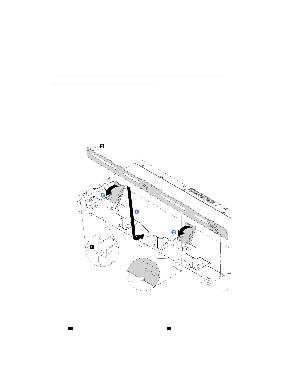
Step 3. Put the backplane down into place.
Figure 39. Installation of backplane for four 3.5-inch hot-swap drives
a. Put the backplane under the front I/O assembly cables, align it with the chassis, and lower it
into the chassis. Put the backplane into place with it leaning backward slightly so that the three
pins
1 on the chassis pass through the three holes 2 in the backplane.
b. Close the release latches to secure the backplane in place.
98
ThinkSystem SR630 V2 Maintenance Manual

 Loading...


