Table 37. VMD domain matrix
Server model
CPU 0 CPU 1
VMD domain VMD domain VMD domain VMD domain
PCIe 1 PCIe 2
1
A
1
B
1
C
1
D
PCIe 3 PCIe 4 PCIe 5 PCIe 6
– 6 SATA/SAS + 2
AnyBay + 2 NVMe
– 6 SATA/SAS + 4
NVMe
6 7 8 9
6 SATA/SAS + 4
AnyBay
6 7 8 9
– 10 AnyBay
– 10 NVMe
0 1 2 3 4 5 6 7 8 9
16 EDSFF
15 14 13 12 11 10 9 8 7 6 5 4 3 2 1 0
Technical rules for PCIe adapters
Understanding the technical rules for PCIe adapters helps you correctly install and configure PCIe adapters
in the system.
PCIe adapters supported for different models
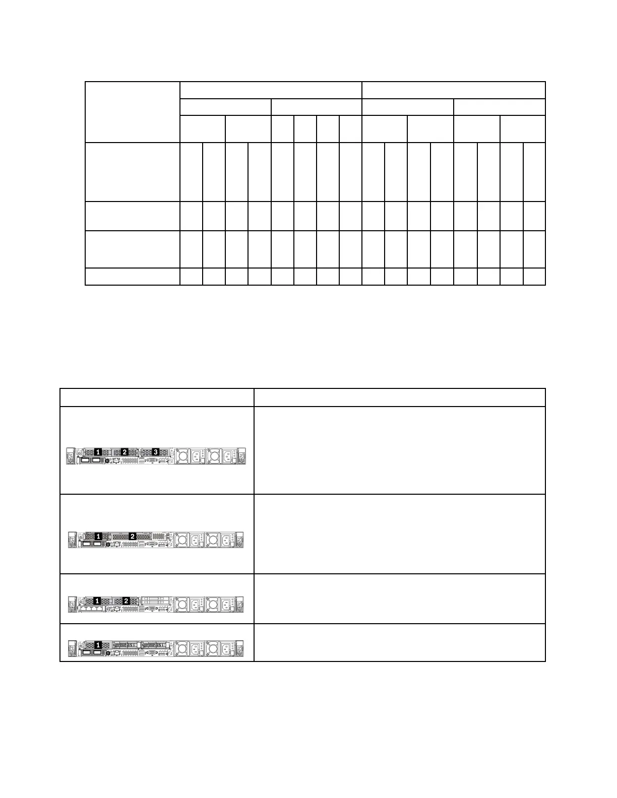
Table 38. PCIe adapters supported and their locations
Server rear view Supported types and slot location
Riser 1 assembly
• Slot 1: PCIe x16 (x8, x4, x1), low-profile
• Slot 2: PCIe x16 (x8, x4, x1), low-profile
Riser 2 assembly
• Slot 3: PCIe x16 (x8, x4, x1), low-profile
Riser 1 assembly
• Slot 1: PCIe x16 (x8, x4, x1), low-profile
• Slot 2: PCIe x16 (x8, x4, x1), full-height
Note: One rear wall bracket must be installed next to the two PCIe
slots.
Riser 1 assembly
• Slot 1: PCIe x16 (x8, x4, x1), low-profile
• Slot 2: PCIe x16 (x8, x4, x1), low-profile
Riser 1 assembly
• Slot 1: PCIe x16 (x8, x4, x1), low-profile
To locate the PCIe slots, see “Rear view” on page 39.
PCIe adapter installation rules and order
When installing different types of PCIe adapters, refer to the following suggested installation priority:
88
ThinkSystem SR630 V2 Maintenance Manual

 Loading...


