Front I/O
Use the section to understand the cable routing for Front I/O.
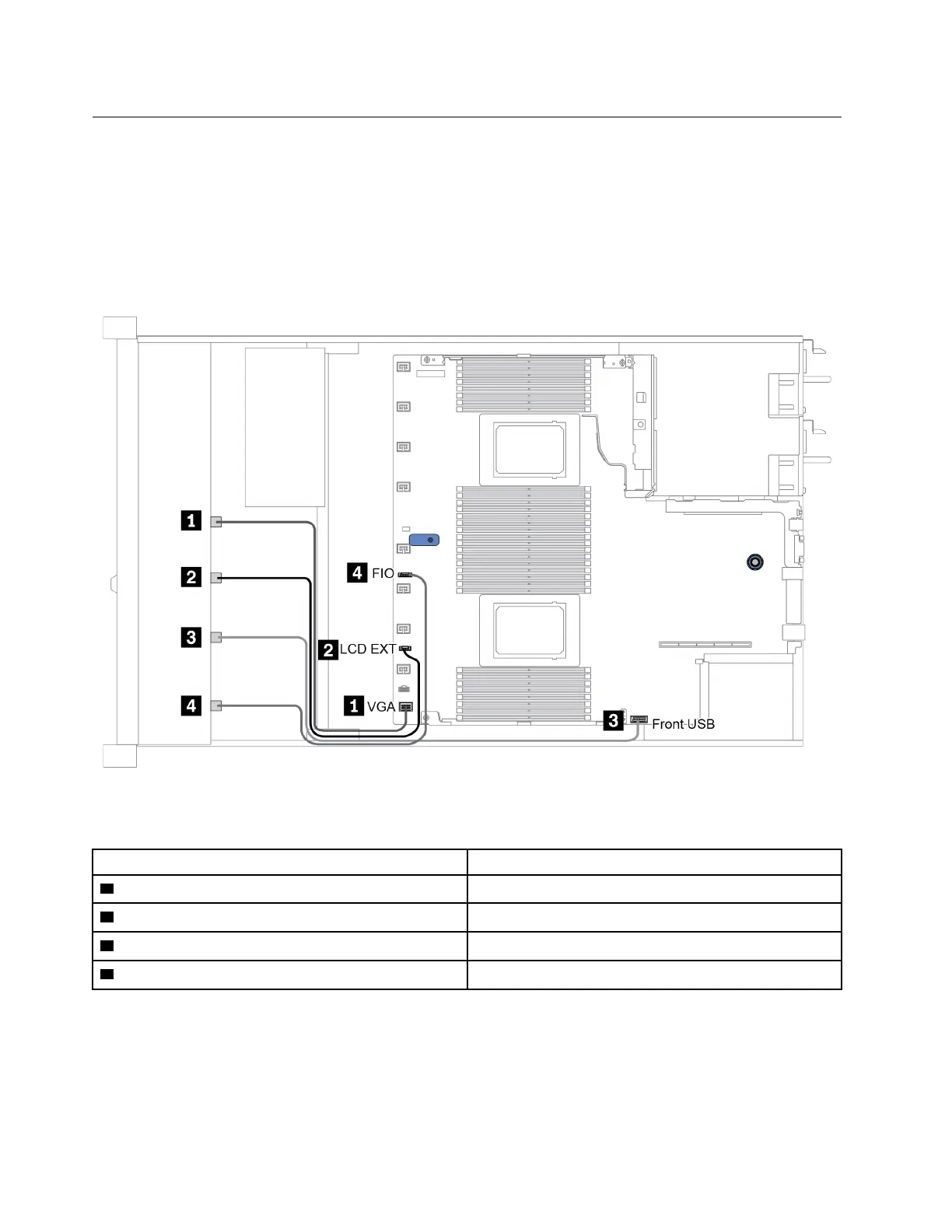
Cable routing for Front I/O
Note: The illustration shows the cabling scenario for server models with four 3.5-inch front drive bays.
Location of each connector on the front of the server varies by models. For detailed location of front I/O
components for different models, see “Front view” on page 19.
Figure 14. Cable routing for Front I/O
From To
1 VGA cable VGA connector on the system board
2 LCD external diagnostics handset cable LCD EXT connector on the system board
3 USB cable Front USB connector on the system board
4 Front diagnostic panel cable
FIO connector on the system board
58 ThinkSystem SR630 V2 Maintenance Manual

 Loading...


