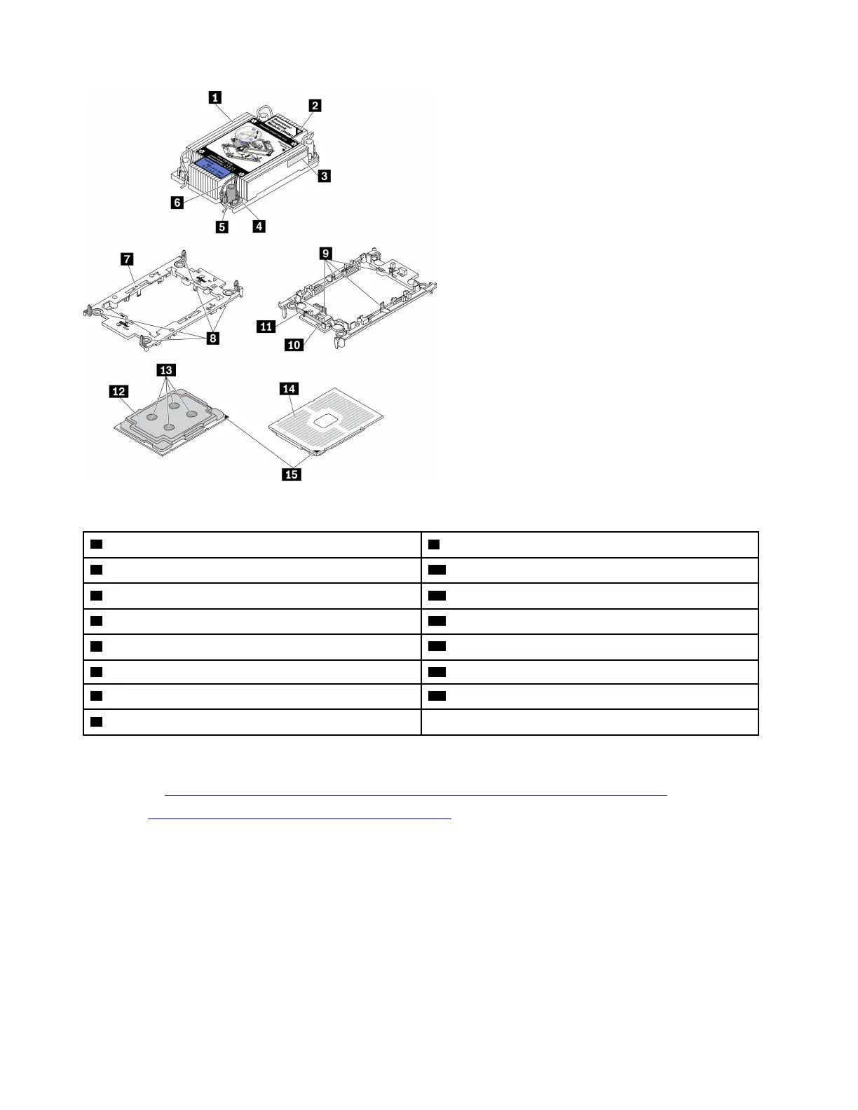
Figure 100. PHM components
1 Heat sink
9 Clips to secure processor in carrier
2 Heat sink triangular mark
10 Carrier triangular mark
3 Processor identification label
11 Processor ejector handle
4 Nut and wire bail retainer 12 Processor heat spreader
5 Torx T30 nut 13 Thermal grease
6 Anti-tilt wire bail 14 Processor contacts
7 Processor carrier 15 Processor triangular mark
8 Clips to secure carrier to heat sink
A video for this task is available at:
• YouTube:
https://www.youtube.com/playlist?list=PLYV5R7hVcs-Cmxb8e4L4PvMQ7J5PxvuOK
• Youku: https://list.youku.com/albumlist/show/id_59643656
Procedure
Step 1. Remove the top cover. See “Remove the top cover” on page 220.
Step 2. Remove the PHM from the system board.
178
ThinkSystem SR630 V2 Maintenance Manual

 Loading...


