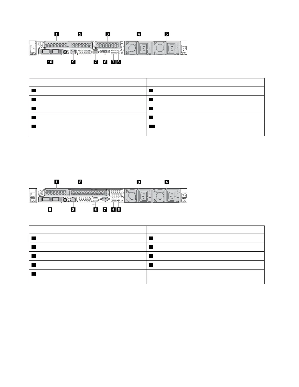
Table 14. Components on the rear of the server
Callout Callout
1 PCIe slot 1 on riser 1 assembly 2 PCIe slot 2 on riser 1 assembly
3 PCIe slot 3 on riser 2 assembly 4 Power supply 2 (optional)
5 Power supply 1 6 NMI button
7 USB 3.2 Gen 1 (5Gbps) connectors (3 DCIs) 8 VGA connector
9 XClarity Controller network connector 10 Ethernet connectors on OCP 3.0 Ethernet adapter
(optional)
Note: For more information about each component, see “Rear components overview” on page 41.
Server model with two PCIe slots
The following illustration shows the rear view of the server model with two PCIe slots. Depending on the
model, your server might look slightly different from the illustration below.
Table 15. Components on the rear of the server
Callout Callout
1 PCIe slot 1 on riser 1 assembly 2 PCIe slot 2 on riser 1 assembly
3 Power supply 2 (optional)
4 Power supply 1
5 NMI button
6 USB 3.2 Gen 1 (5Gbps) connectors (3 DCIs)
7 VGA connector 8 XClarity Controller network connector
9 Ethernet connectors on OCP 3.0 Ethernet adapter
(optional, two or four connectors may be available)
Note: For more information about each component, see “Rear components overview” on page 41.
Server model with two 2.5-inch hot-swap rear drive bays and one PCIe slot
The following illustration shows the rear view of the server model with two hot-swap drive bays and one PCIe
slot. Depending on the model, your server might look slightly different from the illustration below.
40
ThinkSystem SR630 V2 Maintenance Manual

 Loading...


