Cable routing with an SFF RAID adapter (tri-mode)
The following table shows the mapping relationship between backplane connectors and adapter connectors
when a Gen 4 8i SFF RAID adapter (tri-mode) is installed.
Table 24. Mapping between backplane connectors and adapter connectors when a Gen 4 8i SFF RAID adapter (tri-mode)
is installed
Backplane From To
Front BP (SAS) SAS 0 C0
Note: If a tri-mode RAID adapter is used, only U.3 front drives are supported, and U.2 front drives are not
supported.
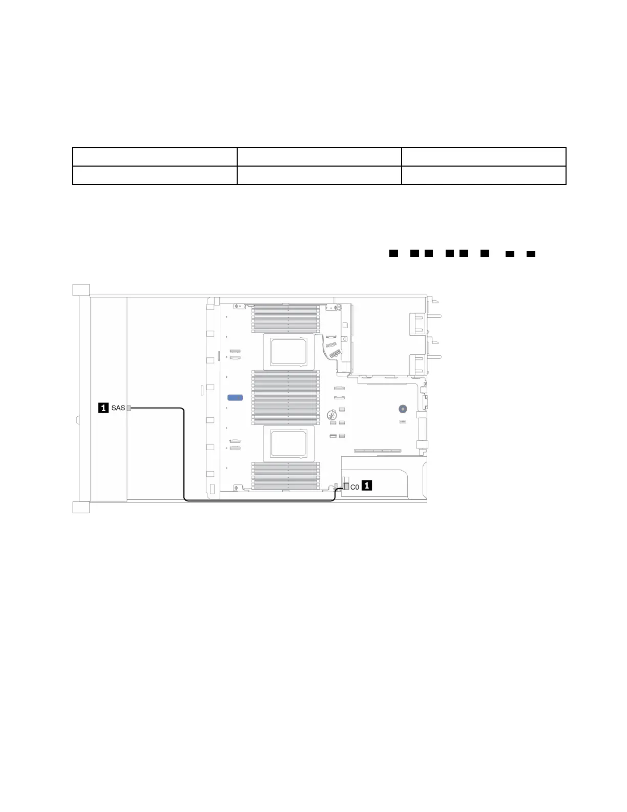
The following figure illustrates the cable routing for the configuration of 4 x 3.5-inch front U.3 drive bays with
a 16i SFF RAID adapter (tri-mode). Connections between connectors:
1 ↔ 1 , 2 ↔ 2 , 3 ↔ 3 , ... n ↔ n
Figure 23. Cable routing for 4 x 3.5-inch front U.3 drive bays with a Gen 4 8i SFF RAID adapter (tri-mode)
Chapter 3. Internal cable routing 69

 Loading...


