Cable routing with a CFF HBA/RAID adapter
The following table shows the mapping relationship between backplane connectors and system board/
adapter connectors when a 16i CFF HBA/RAID adapter is installed.
Table 34. Mapping between backplane connectors and system board/adapter connectors when a 16i CFF HBA/RAID
adapter is installed
Backplanes From To
Front BP (NVMe)
NVMe 0-1, 2-3
PCIe 1, PCIe 2
Front BP (SAS) SAS 0 C0
SAS 1 C1
SAS 2 C2
Rear BP (if any)
SAS C3
NVMe 0, NVMe 1
PCIe 6
Note: For power and input cable connection of the CFF HBA/RAID adapter, refer to “CFF HBA/RAID
adapter” on page 57.
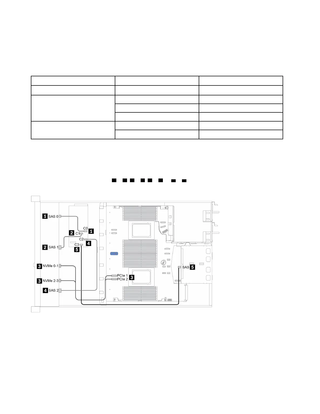
The following figure illustrates the cable routing for the configuration of 10 x 2.5-inch front drive bays (6 x
SAS/SATA + 4 x AnyBay) with a 16i CFF RAID adapter and a rear 2 x 2.5-inch SAS/SATA drive cage.
Connections between connectors:
1 ↔ 1 , 2 ↔ 2 , 3 ↔ 3 , ... n ↔ n
Figure 33. Cable routing for 10 x 2.5-inch front drive bays (6 x SAS/SATA + 4 x AnyBay) with a 16i CFF RAID adapter and
a rear 2 x 2.5-inch SAS/SATA drive cage
82 ThinkSystem SR630 V2 Maintenance Manual

 Loading...


