System bus (CAN) / CANopen
Wiring
7
Electrical installation
7.4
7.4.1
L
7.4−1
EDSPM−TXXX−9.0−11/2009
7.4 System bus (CAN) / CANopen
7.4.1 Wiring
LO
LO LO
CG
CG CG
HI
HI HI
A
2
A
1
A
3
A
n
EPM-T1XX
EPM-T83X
PES PES
PES
PES
PES
PES
CAN-GND
CAN-LOW
CAN-HIGH
120
120
120
1
2
3
4
5
6
7
8
9
epm−t061
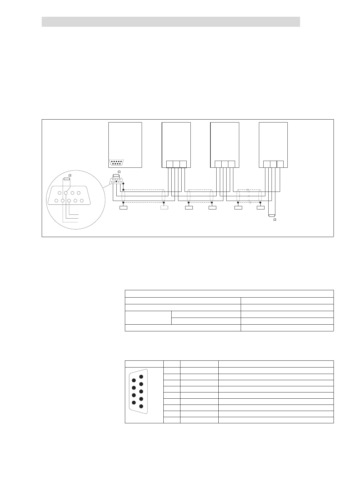
Fig. 7.4−1 Basic wiring of the system bus (CAN) / CANopen
A1 Nodes 1 EPM−T110 or EPM−T8XX
A2 Node 2
A3 Node 3
A
n
Node n (e.g. PLC), n = max. 63
We recommend the use of CAN cables according to ISO 11898−2:
CAN cable according to ISO 11898−2
Cable type Twisted pair with shielding
Impedance 120 W (95 ... 140 W)
Cable resistance
Cable length £ 300 m £ 70 mW/m
Cable length £ 1000 m £ 40 mW/m
Signal propagation delay £ 5 ns/m
7.4.2 Communication connection
View Pin Assignment Explanation
1
2
3
4
5
6
7
8
9
1 Not assigned −
2 CAN−LOW Data line
3 CAN−GND Data ground
4 Not assigned −
5 Not assigned −
6 Not assigned −
7 CAN−HIGH Data line
8 Not assigned −
epm−t023
9 Not assigned −
Specification of the transmission
cable 3
Assignment of Sub−D plug4
 Loading...