4×analog input ±20mA
4
The modular system
4.16
L
4.16−1
EDSPM−TXXX−9.0−11/2009
4.16 4×analog input ±20mA
The module 4×analog input ±20mA has 4 analog inputs. The module assigns a
total of eight bytes of input data in the process image (2 bytes per input). The
analog inputs are isolated with regard to the backplane bus.
) Note!
The chapter "Parameter setting" describes how to parameterise
the module.
l 4 analog inputs
l Current measuring range ± 20 mA
l Signal function and data format can be parameterised
l The reference potentials may vary from each other by a voltage differential of
up to 2 V
l Status LED indicates if the input current is outside of the permitted
measuring range
0
1
2
epm−t015
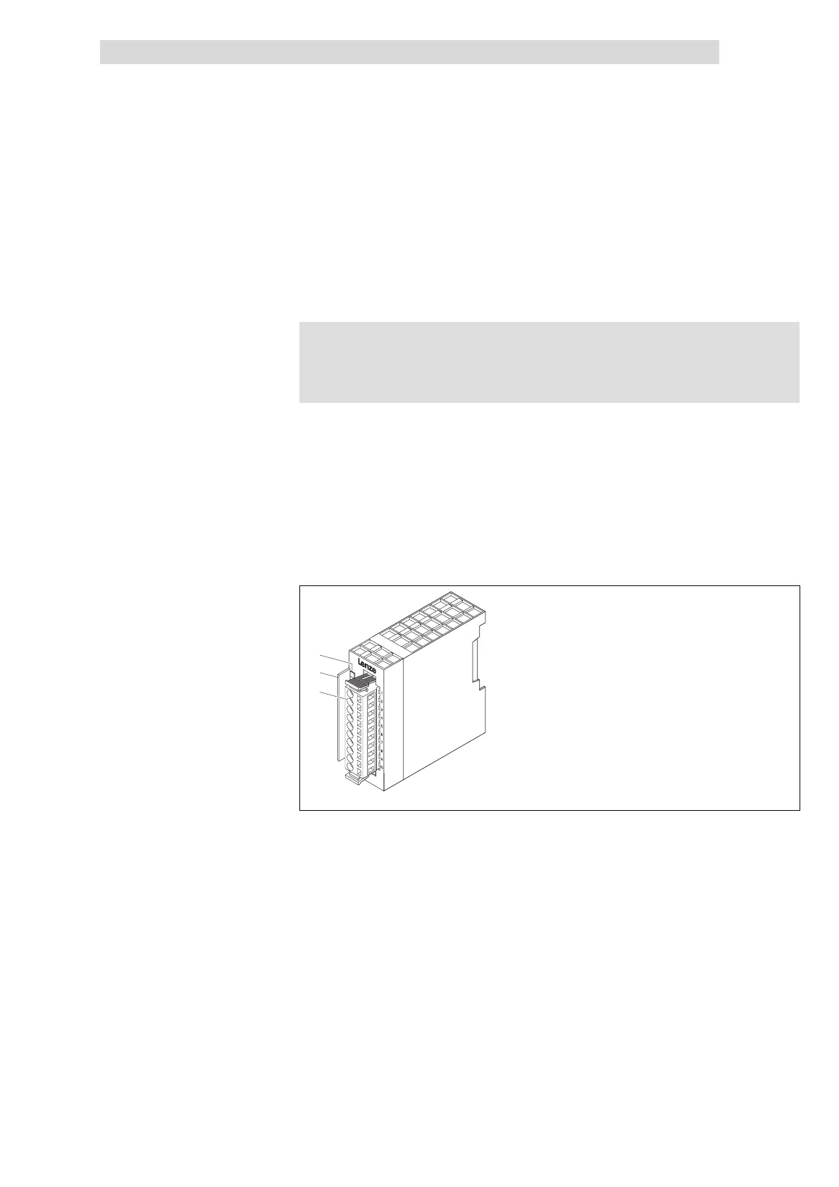
Fig. 4.16−1 Overview of 4×analog input ±20mA
LED for status display
Bit address label card
Plug−in terminal strip
Description
Features
Overview
 Loading...