4×analog input ±20mA
4
The modular system
4.16
L
4.16−2
EDSPM−TXXX−9.0−11/2009
( Stop!
The module will be destroyed if the connected signals or encoders
do not match the set measuring range:
AI 4x12BIT 20mA
F
1
2
3
4
5
6
7
8
9
L
10
EPM – T312 1A 10
1
0
2
1
3
5
7
9
10
4
6
8
.
D
A
µP
MUX
PES
PES
PES
PES
epm−t216 epm−t215
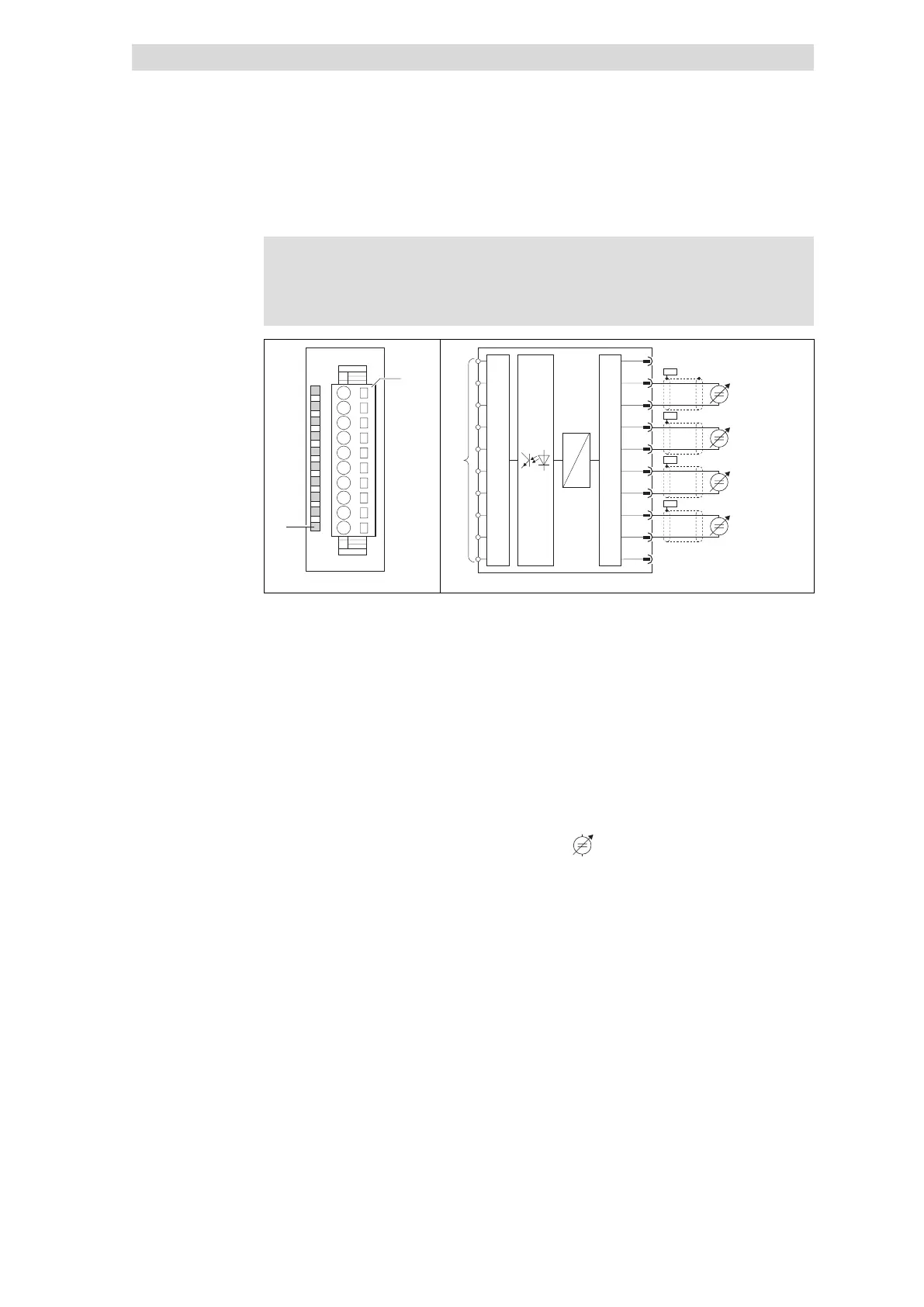
Fig. 4.16−2 Front view of 4×analog input ±20mA
Status display F; LED (red)
Is lit if the input voltage is outside
of the permitted measuring range
Terminal strip assignment details
1 Not assigned
2 + / analog input E.0
3 − / analog input E.0
3 + / analog input E.1
5 − / analog input E.1
6 + / analog input E.2
7 − / analog input E.2
8 + / analog input E.3
9 − / analog input E.3
10 Not assigned
Connection to backplane bus
Current source
PES HF shield termination through
large−surface connection to PE
l
Short−circuit unused inputs (connect positive and negative terminals) or
deactivate them by setting parameters.
l The module does not provide any auxiliary supply for sensors / actuators.
For information on how to connect an auxiliary supply, please see the
documentation for the sensors / actuators.
Status display and terminal
assignment
 Loading...