8×digital output 0.5A
4
The modular system
4.7
L
4.7−1
EDSPM−TXXX−9.0−11/2009
4.7 8×digital output 0.5A
The module 8×digital output 0.5A detects the binary control signals from the
master bus system and transports them to the process level via the outputs. The
digital outputs are supplied via an external voltage source (DC 24 V).
) Note!
The chapter "Parameter setting" describes how to parameterise
the module.
l 8 digital outputs
l DC 24 V supply voltage
l Each digital output has a load capacity of up to 0.5 A
l Suitable for solenoid valves and DC contactors
l LED displays the states of the digital outputs
0
1
2
epm−t015
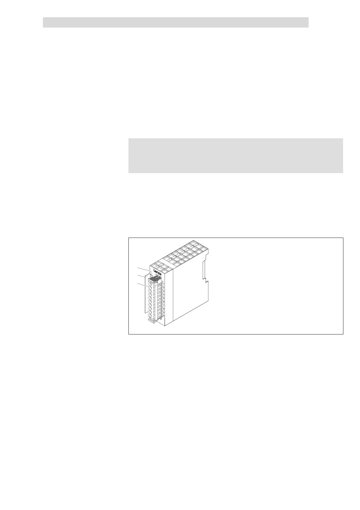
Fig. 4.7−1 Overview of 8×digital output 0.5A
LED for status display
Bit address label card
Plug−in terminal strip
Description
Features
Overview
 Loading...