Parameterising SSI interface
Input data / output data
13
Parameter setting via PROFIBUS−DP
13.3
13.3.2
L
13.3−3
EDSPM−TXXX−9.0−11/2009
13.3.2 Input data / output data
L
X1
PW
ER
RD
DE
DC
24V
+
-
EPM – T120 xx.xx
A
D
R
.
64
32
16
8
4
2
1
–
1
0
Data to module
Control
Data In HB
DataInMB
DataInLB
Status
Data Out HB
Data Out MB
Data Out LB
0
E/A.1
E/A.0
SSI
Encoder
0112233
Data from module
Gateway SSI-Interface
.0
.1
.2
.3
.4
.5
.6
.7
1
2
3
4
5
6
7
8
9
L
10
+24 V
Hold
E/A.0
epm−t250
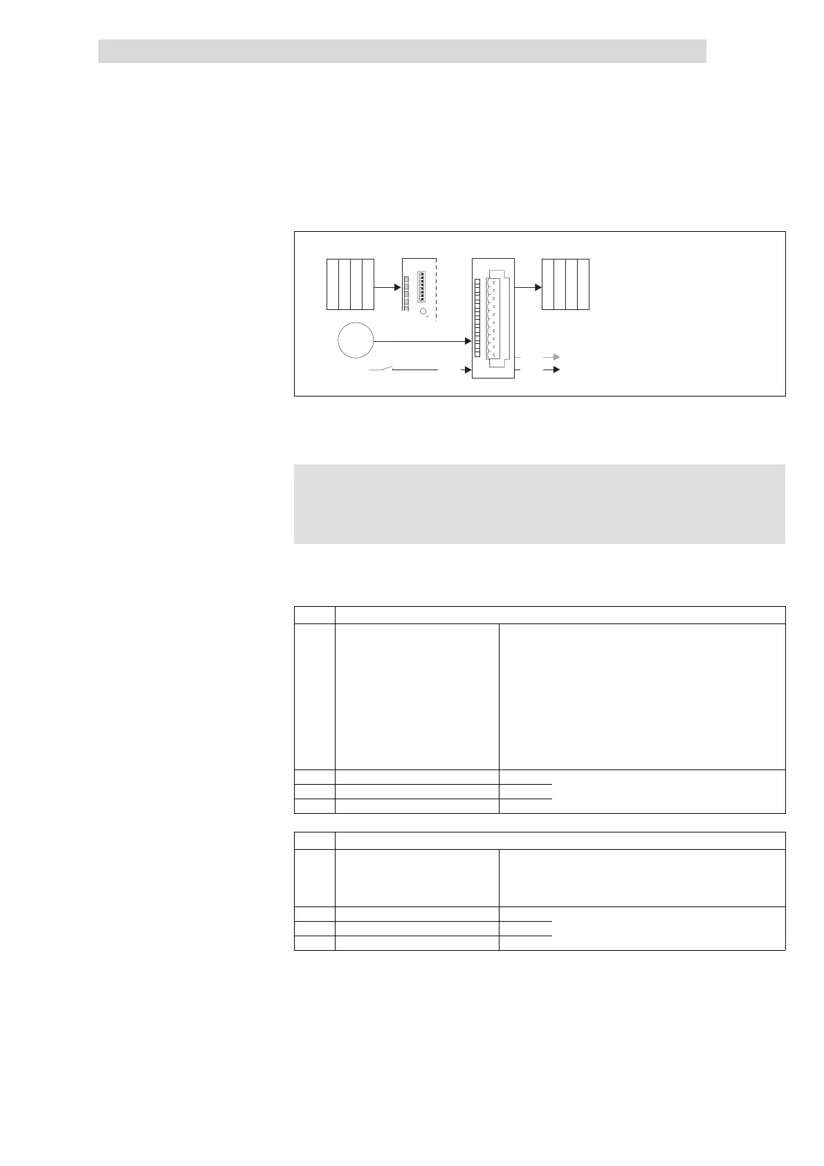
Fig. 13.3−1 Data input /output of SSI interface
For the data input / data output, 4 bytes are available which are transmitted to the
module or output by the module.
) Note!
Input and output data are lost when the supply voltage is
disconnected; they are not saved!
The input data can be used to control the outputs (I/O.0 and I/O.1) depending on
the encoder value.
Byte Assignment
0 Control Bits 0 ... 1
%
Setpoint selection
00: No setpoint selection
01: Setpoint selection for output I/O.0
10: Setpoint selection for output I/O.1
11: Setpoint selection for outputs I/O.0 and I/O.1
Bit 2 Reserved
Bit 3
Condition for setting the output = HIGH
0: If SSI encoder value is higher than setpoint
1: If SSI encoder value is lower than setpoint
Bits 4 ... 7 Reserved
1 Comparison value (HIGH byte) Bits 0 ... 7
Selection of comparison value
2 Comparison value (MID byte) Bits 0 ... 7
3 Comparison value (LOW byte) Bits 0 ... 7
Byte Assignment
0 Status
Bit 0 Status I/O.0
Bit 1 Status I/O.1
Bits 2 ... 7
%
Reserved
1 SSI encoder value (HIGH byte) Bits 0 ... 7
Output of SSI encoder value
2 SSI encoder value (MID byte) Bits 0 ... 7
3 SSI encoder value (LOW byte) Bits 0 ... 7
Input data
Output data
 Loading...