Transmitting process data
Compatibility with Lenze drive and automation components
9
Network via CANopen
9.3
9.3.7
L
9.3−9
EDSPM−TXXX−9.0−11/2009
9.3.7 Compatibility with Lenze drive and automation components
The tables below will assist you in finding out at which stage a modular system or
which compact module, respectively, can be operated in combination with a Lenze
drive and automation component.
Compatibility is dependent on the available process data objects (PDO).
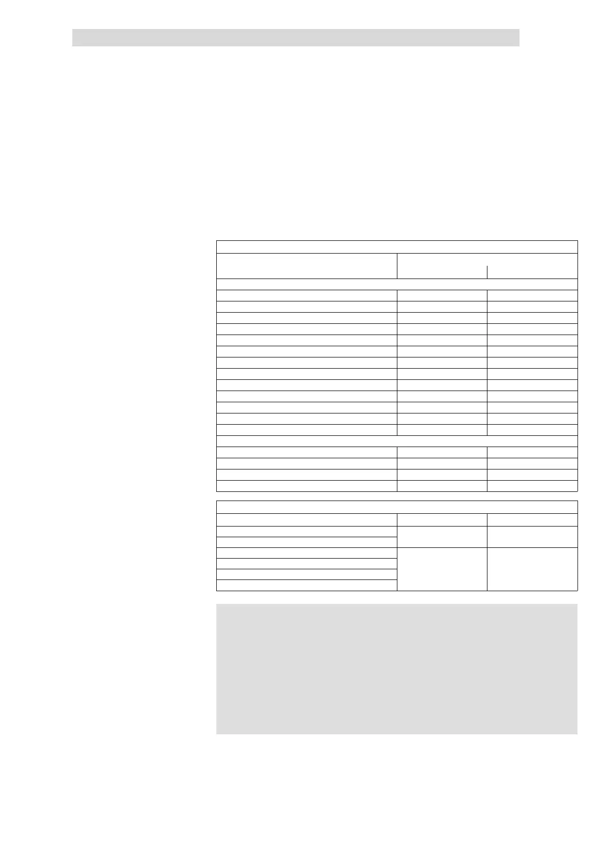
Process data objects (PDO) of the I/O system IP20 (slave)
Module type Module requires
PDO−Rx PDO−Tx
Modular system
8×digital input — 1/8
16×digital input — 2/8
8×digital output 1A 1/8 —
8×digital output 2A 1/8 —
16×digital output 1A 2/8 —
8×digital input / output 1/8 1/8
4×relay 1/8 —
4×analog input — 8/8
4×analog output 8/8 —
4×analog input / output 8/8 8/8
2/4×counter 8/8 + 2/8 8/8 + 1/8
SSI interface 8/8 8/8
1×counter/16×digital input 8/8 8/8
Compact system
8×dig. I/O compact 8/8 8/8
16×dig. I/O compact 8/8 8/8
16×dig. I/O compact (single−wire conductor) 8/8 8/8
16×dig. I/O compact (three−wire conductor) 8/8 8/8
Process data objects (PDO) of the Lenze drive and automation components (master)
Components PDO−Rx [x
PDO−Rx
] PDO−Tx [x
PDO−Tx
]
9300 Servo PLC
>10 >10
Drive PLC
9300 inverter (all standard types)
2 2
8200 vector frequency inverter
8200 motec frequency inverter
Communication module EMF2175
) Note!
l A modular system allows the connection of max. 32 modules in
addition to the CAN gateway.
l A modular system offers max. 20 PDOs (10 PDO−Rx and
10 PDO−Tx) for process data exchange.
l Since 9300 Servo PLC and Drive PLC are able to manage more
than 20 process data objects, several modular systems can be
operated on a Servo PLC or Drive PLC. For this each CAN
gateway must be assigned to a unique node address.
A control task requires the connection of 4 digital outputs, 10 digital inputs and
3 analog outputs to an 8200 vector frequency inverter.
Example
 Loading...